IL17569
Page 5-44
Effective June, 2001
In:
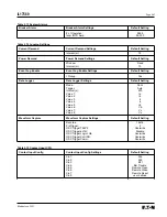
This setting defines the logic input to Timer Gates
1 through 6. See the settings table and Section
9 for a complete description of the logic
input settings.
On Delay (c) :
Sets the number of cycles the Timer Gate input
must remain active before the Timer Gate output
becomes active. See Section 9 for a detailed
description of the logic settings.
Off Delay (c) :
Sets the number of cycles the Timer Gate
output will remain active after the Timer Gate
input becomes inactive. The Off Delay has no
affect unless the Timer Gate output is active
when the input becomes inactive. See Section
9 for a detailed description of the logic settings.
Logic Latches 1
Both logic latches contain the same settings as
and 2:
shown below.
Setting Group:
This setting defines the Setting Group for which
the logic latch programming is active. This setting
is also linked to the System Config settings, which
is where the total number of settings groups (1
to 4) is programmed.
Set In:
This setting defines the Set Input to the Logic
Latch. The latch output goes active when the
Set Input is active. The output remains latched
in the active state until the Reset is activated.
See the settings table and Section 9 for a
complete description of the logic input settings.
Reset In:
This setting defines the Reset Input to the Logic
Latch. The latch output is reset when the Reset
Input is active. If both the Set Input and Reset
Input are active, the latch output is inactive.
See the settings table and Section 9 for a
complete description of the logic input settings.
Blocking Logic
All 12 blocking logic gates contain the same
Gates for IOC
settings as shown below. When the output of
and TOC:
the blocking logic gate is active, operation of
the associated IOC or TOC protection function
is blocked. The IOC or TOC function will still
pickup, but not trip.
Function:
Set to OR, AND, NOR, NAND, Disable. The
Function setting defines the output of the blocking
logic gates with inputs IN1, IN2, IN3, and IN4.
The default setting is Disable. See Section 9 for
a detailed description of the logic settings.
Setting Group:
This setting defines the Setting Group for which
the logic gate programming is active. This setting
is also linked to the System Config settings,
which is where the total number of settings
groups (1 to 4) is programmed.
IN1, IN2, IN3, IN4:
These settings define the logic inputs to Logic
Gates 1 through 6. See the settings table and
Section 9 for a complete description of the logic
input settings.
5.5.8 Clock Settings
Once the FP-5000 is properly installed, the real-time clock needs to
be set, to get the right date and time for clock display, and all
Metering and Logging date and time stamp values.
To set the clock, select the clock setting in the “Setting Main”
display window. Configure the settings below to set the clock.
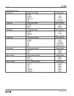
Date Mode:
Sets the mode for the date used in all time
stamp displays.
Time Mode:
Sets the mode for the time used in all time
stamp displays.
Year:
Sets the current year for the real-time
clock update.
Month:
Sets the current month for the real-time
clock update.
Day:
Sets the current day for the real-time
clock update.
Hour:
Sets the current hour for the real-time
clock update.
Minute:
Sets the current minute for the real-time
clock update.
Second:
Sets the current second for the real-time
clock update.
Update Clock:
Pressing Enter updates the clock with the date
and time specified above, with the message
stating that the real-time clock was
properly updated.
5.5.9 Communications Settings
To set the communications settings, select the Communications
setting in the “Setting Main” display window. Configure the settings
below to set the communications desired.
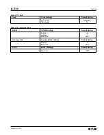
INCOM PN
Provides connection to the IMPACC network for communication
over PowerNet. The standard IMPACC messages are supported.
Enable:
Enables INCOM Communication.
Address:
Sets the device address for INCOM
communication.
Baud Rate:
Sets the baud rate for INCOM communication.
The baud rate is fixed at 9600 baud.
INCOM AB
Provides an additional INCOM channel for future expansion to
interconnect function modules for analog and digital I/O accessories.
Address:
Sets the device address for Communication
through Accessory bus.
Baud Rate:
Sets the baud rate for Accessory bus
communication. The baud rate is fixed
at 9600 baud.
RS-232
Provides connection to a personal computer for downloading code
and/or downloading settings for FP-5000.
Baud Rate:
Sets the baud rate for RS-232 communication.
Summary of Contents for Cutler-Hammer FP-5000
Page 1: ...IL17569 Effective June 2001 Instructions for FP 5000 Protective Relay...
Page 7: ...IL17569 Table of Contents 6 Effective June 2001 This page left blank intentionally...
Page 13: ...IL17569 Page 2 2 Effective June 2001 Figure 2 2 FP 5000 Simple Wye Connected Application...
Page 14: ...Page 2 3 IL17569 Effective June 2001 Figure 2 3 FP 5000 Simple Open Delta Application...
Page 19: ...IL17569 Page 2 8 Effective June 2001 This page left blank intentionally...
Page 25: ...IL17569 Page 3 6 Effective June 2001 This page left blank intentionally...
Page 98: ...IL17569 Page 5 50 Effective June 2001 This page left blank intentionally...
Page 108: ...IL17569 Page 6 10 Effective June 2001 Figure 6 10 Common Ct Wiring Configurations...
Page 141: ...IL17569 Page 11 4 Effective June 2001 This page left blank intentionally...
Page 165: ...IL17569 Page Appendix 6 Effective June 2001 Figure 13 2 ANSI Very Inverse...
Page 166: ...Page Appendix 7 IL17569 Effective June 2001 Figure 13 3 ANSI Extremely Inverse...
Page 167: ...IL17569 Page Appendix 8 Effective June 2001 Figure 13 4 IEC A Figure 13 4 IEC A...
Page 168: ...Page Appendix 9 IL17569 Effective June 2001 Figure 13 5 IEC B...
Page 169: ...IL17569 Page Appendix 10 Effective June 2001 Figure 13 6 IEC C...
Page 170: ...Page Appendix 11 IL17569 Effective June 2001 Figure 13 7 IEC...
Page 171: ...IL17569 Page Appendix 12 Effective June 2001 Figure 13 8 ANSI...
Page 172: ...Page Appendix 13 IL17569 Effective June 2001 Figure 13 9 Thermal...
Page 173: ...IL17569 Page Appendix 14 Effective June 2001 Figure 13 10 Phase I4 t...
Page 174: ...Page Appendix 15 IL17569 Effective June 2001 Figure 13 11 Phase I2 t...
Page 175: ...IL17569 Page Appendix 16 Effective June 2001 Figure 13 12 Phase It...
Page 176: ...Page Appendix 17 IL17569 Effective June 2001 Figure 13 13 Phase 12 I4 t...
Page 177: ...IL17569 Page Appendix 18 Effective June 2001 Figure 13 14 Phase I2 t...
Page 178: ...Page Appendix 19 IL17569 Effective June 2001 Figure 13 15 Ground IT...
Page 180: ...Page Appendix 21 IL17569 Effective June 2001 This page left blank intentionally...
Page 187: ...Publication No IL17569 June 2001 Pittsburgh Pennsylvania U S A...


