


Operation
83
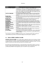
6.6 MANUAL MODE
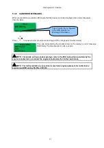
NOTE: If a digital input configured to
panel lock
is active, changing module modes will
not be possible. Viewing the instruments and event logs is NOT affected by panel lock.
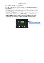
Activate Manual mode be pressing the
pushbutton. An LED indicator beside the button confirms
this action.
Manual mode allows the operator to start and stop the set manually, and if required change the state
of the load switching devices.
6.6.1 WAITING IN MANUAL MODE
When in manual mode, the set will not start automatically.
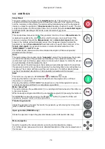
To begin the starting sequence, press the
button.
6.6.2 STARTING SEQUENCE
NOTE: There is no
start delay
in this mode of operation.
The fuel relay is energised and the engine is cranked.
NOTE: If the unit has been configured for CAN, compatible ECU’s will receive the start
command via CAN.
If the engine fails to fire during this cranking attempt then the starter motor is disengaged for the
crank
rest
duration after which the next start attempt is made. Should this sequence continue beyond the set
number of attempts, the start sequence will be terminated and the display shows
Fail to Start.
When the engine fires, the starter motor is disengaged. Speed detection is factory configured to be
derived from the main alternator output frequency but can additionally be measured from a Magnetic
Pickup mounted on the flywheel (Selected by PC using the 8600 series configuration software).
Additionally, rising oil pressure or charge alternator voltage can be used to disconnect the starter
motor (but cannot detect underspeed or overspeed).
NOTE: If the unit has been configured for CAN, speed sensing is via CAN.
After the starter motor has disengaged, the
Safety On
timer activates, allowing Oil Pressure, High
Engine Temperature, Under-speed, Charge Fail and any delayed Auxiliary fault inputs to stabilise
without triggering the fault.
Summary of Contents for DSE8610
Page 47: ...Installation 47 4 2 2 3 PHASE 4 WIRE WITHOUT EARTH FAULT PROTECTION...
Page 51: ...Installation 51 4 3 2 SINGLE PHASE WITHOUT EARTH FAULT...
Page 53: ...Installation 53 4 3 4 2 PHASE L1 L2 3 WIRE WITHOUT EARTH FAULT...
Page 55: ...Installation 55 4 3 6 2 PHASE L1 L3 3 WIRE WITHOUT EARTH FAULT MEASURING...
Page 118: ...Intentionally Left Blank 118...


