


Installation
42
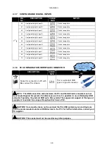
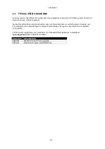
Connection of CT s1 terminal
PIN
No
DESCRIPTION
CABLE
SIZE
NOTES
51
CT Secondary for Gen L1
2.5mm²
AWG 13
Connect to s1 secondary of L1 monitoring CT
52
CT Secondary for Gen L2
2.5mm²
AWG 13
Connect to s1 secondary of L2 monitoring CT
53
CT Secondary for Gen L3
2.5mm²
AWG 13
Connect to s1 secondary of L3 monitoring CT
Connection to terminals 54 & 55
The function of terminals 54 and 55 CHANGES depending upon what kind of earth fault protection (if any) is being used:
Topology
Pin
No
Description
CABLE
SIZE
No earth fault measuring
54
DO NOT CONNECT
55
Connect to s2 of the CTs connected to
L1,L2,L3,N
2.5mm²
AWG 13
Restricted earth fault measuring
54
Connect to s2 of the CTs connected to
L1,L2,L3,N
2.5mm²
AWG 13
55
Connect to s1 of the CT on the neutral
conductor
2.5mm²
AWG 13
Un-restricted earth fault measuring
(Earth fault CT is fitted in the neutral to
earth link)
54
Connect to s1 of the CT on the neutral
to earth conductor.
2.5mm²
AWG 13
55
Connect to s2 of the CT on the neutral
to earth link.
Also connect to the s2 of CTs
connected to L1, L2, L3.
2.5mm²
AWG 13
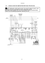
NOTE: Take care to ensure correct polarity of the CT primary as shown overleaf. If in
doubt, check with the CT supplier.
NOTE: Terminals 56 to 59 are not fitted to the 8610 series controller.
Summary of Contents for DSE8610
Page 47: ...Installation 47 4 2 2 3 PHASE 4 WIRE WITHOUT EARTH FAULT PROTECTION...
Page 51: ...Installation 51 4 3 2 SINGLE PHASE WITHOUT EARTH FAULT...
Page 53: ...Installation 53 4 3 4 2 PHASE L1 L2 3 WIRE WITHOUT EARTH FAULT...
Page 55: ...Installation 55 4 3 6 2 PHASE L1 L3 3 WIRE WITHOUT EARTH FAULT MEASURING...
Page 118: ...Intentionally Left Blank 118...


