


Operation
79
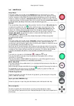
STOP mode is activated by pressing the
button.
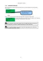
NOTE:
Enable
Cool Down in Stop Mode
option has been added to version 6.0
In STOP mode, the module will immediately remove the generator from load (if necessary) before
stopping the engine if it is already running.
•
If
Cool Down in Stop Mode
not enabled, no cooling run is provided for this operation. Where a
cooling run is required, switch to MANUAL mode and open the breaker manually. Allow the
set to cool off load, before pressing the STOP button to stop the engine.
•
If
Cool Down in Stop Mode
enabled, cooling run is provided for this operation. The set will run
off load for the amount of time configured in
Load/Stopping Timers, Cooling Time
before the
set is stopped.
If the engine does not stop when requested, the FAIL TO STOP alarm is activated (subject to the
setting of the
Fail to Stop
timer). To detect the engine at rest the following must occur:
•
Engine speed is zero as detected by the Magnetic Pickup or CANbus ECU (depending upon
module variant).
•
Generator frequency must be zero.
•
Oil pressure switch must be closed to indicate low oil pressure (MPU version only)
When the engine has stopped, it is possible to send configuration files to the module from DSE
Configuration Suite PC software and to enter the Front Panel Editor to change parameters.
Any latched alarms that have been cleared will be reset when STOP mode is entered.
The engine will not be started when in STOP mode. If remote start signals are given, the input is
ignored until AUTO mode is entered.
When configured to do so, when left in STOP mode for five minutes with no presses of the fascia
buttons, the module enters low power mode. To ‘wake’ the module, press the
button or any other
fascia control button.
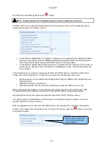
Sleep mode configuration
in the DSE Configuration
Suite Software
Summary of Contents for DSE8610
Page 47: ...Installation 47 4 2 2 3 PHASE 4 WIRE WITHOUT EARTH FAULT PROTECTION...
Page 51: ...Installation 51 4 3 2 SINGLE PHASE WITHOUT EARTH FAULT...
Page 53: ...Installation 53 4 3 4 2 PHASE L1 L2 3 WIRE WITHOUT EARTH FAULT...
Page 55: ...Installation 55 4 3 6 2 PHASE L1 L3 3 WIRE WITHOUT EARTH FAULT MEASURING...
Page 118: ...Intentionally Left Blank 118...


