


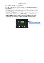
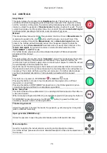


Description Of Controls
63
5.3.3 ENGINE
Contains instrumentation gathered about the engine itself, some of which may be obtained using the
CAN or other electronic engine link.
•
Engine Speed
•
Oil Pressure
•
Coolant Temperature
•
Engine Battery Volts
•
Run Time
•
Oil Temperature*
•
Coolant Pressure*
•
Inlet Temperature*
•
Exhaust Temperature*
•
Fuel Temperature*
•
Turbo Pressure*
•
Fuel Pressure*
•
Fuel Consumption*
•
Fuel Used*
•
Fuel Level*
•
Auxiliary Sensors (If fitted and configured)
•
Engine Maintenance Due (If configured)
•
Engine ECU Link*
*When connected to suitably configured and compatible engine ECU. For details of supported engines
see ‘Electronic Engines and DSE wiring’ (DSE Part number 057-004).
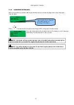
Depending upon configuration and instrument function, some of the instrumentation items may include
a tick
icon beside them. This denotes a further function is available, detailed in the ‘operation’
section of this document.
Example:
The tick
icon denotes that manual fuel pump control is
enabled in this system.
Press and hold to start the fuel transfer pump, release to
stop the pump. This is detailed further in the section entitled
‘operation’ elsewhere in this document.
Summary of Contents for DSE8610
Page 47: ...Installation 47 4 2 2 3 PHASE 4 WIRE WITHOUT EARTH FAULT PROTECTION...
Page 51: ...Installation 51 4 3 2 SINGLE PHASE WITHOUT EARTH FAULT...
Page 53: ...Installation 53 4 3 4 2 PHASE L1 L2 3 WIRE WITHOUT EARTH FAULT...
Page 55: ...Installation 55 4 3 6 2 PHASE L1 L3 3 WIRE WITHOUT EARTH FAULT MEASURING...
Page 118: ...Intentionally Left Blank 118...


