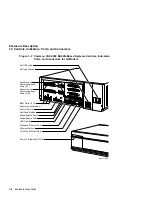
Enclosure Description
1.2 Controls, Indicators, Ports, and Connectors
Table 1–1 (Cont.) Functions of the Controls, Indicators, Ports, and Connectors
Component
Description
Break/enable switch
5
A two-position switch that determines the function of MMJ
port 3 as follows:
•
Up position—MMJ port 3 functions as a console port.
In this state, you can press the Break key on the
keyboard of a terminal connected to MMJ port 3 to put
the system in console mode.
•
Down position—MMJ port 3 functions as a normal
communications port. MMJ port 0 functions as a
console port.
Break/enable LED
6
A LED indicator that shows the function of MMJ port 3 as
follows:
•
On—MMJ port 3 functions as a console port.
•
Off—MMJ port 3 functions as a normal communications
port.
LED display
A set of eight LEDs that provide power-up and self-
test diagnostic code information. This is useful for fault
diagnosis when the console terminal is not functioning.
Standard Ethernet port
A port that allows you to connect the system to a standard
Ethernet network.
Ethernet switch
A two-position switch that determines the type of Ethernet
that the system uses as follows:
•
Left position—selects the standard Ethernet type
•
Right position—selects the ThinWire™ Ethernet type
ThinWire Ethernet port
A port that allows you to connect the system to a ThinWire
Ethernet network.
5
The system recognizes the position of this switch only when you turn on the power.
6
Light emitting diode (LED).
1–8 Enclosure Description


