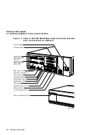
Enclosure Description
1.2 Controls, Indicators, Ports, and Connectors
Table 1–1 Functions of the Controls, Indicators, Ports, and Connectors
Component
Description
On/Off switch
Applies and stops the power to the system unit as follows:
•
On ( | )—Applies the ac power to the system unit
•
Off (O)—Stops the ac power to the system unit
System ac power socket
A socket for the ac power input.
SCSI
1
port
A port that allows you to connect external SCSI devices.
Synchronous communi-
cations ports (0,1)
2
Two ports that allow you to connect devices that have
synchronous communications support.
Asynchronous communi-
cations ports (A,B)
2
One or two ports that provide one of the following
asynchronous communications expansion options:
•
Eight DEC423 compatible asynchronous ports
•
Sixteen DEC423 compatible asynchronous ports
•
Eight EIA-232 compatible modem ports
MMJ
3
port 0
DEC423 compatible asynchronous port. This port is the
primary console port.
MMJ port 1
DEC423 compatible asynchronous port.
MMJ port 3
DEC423 compatible asynchronous port. This port functions
as an alternate console port when the break/enable switch
is set in the up position when you turn on the system unit.
Asynchronous modem
control port (2)
EIA-232 compatible asynchronous port with modem control.
DSSI Connector
4
Ports for the management of integrated storage products.
Q–bus Connectors
Q–bus expansion port which connects the expansion
enclosure.
Halt push button
A momentary-contact push button that puts the system in
console mode.
1
Small computer system interface (SCSI).
2
Optional ports that depend on the system configuration.
3
Modified modular jack (MMJ).
4
Digital Storage Systems Interconnect (DSSI); up to three in some optional configurations.
(continued on next page)
Enclosure Description 1–7


