


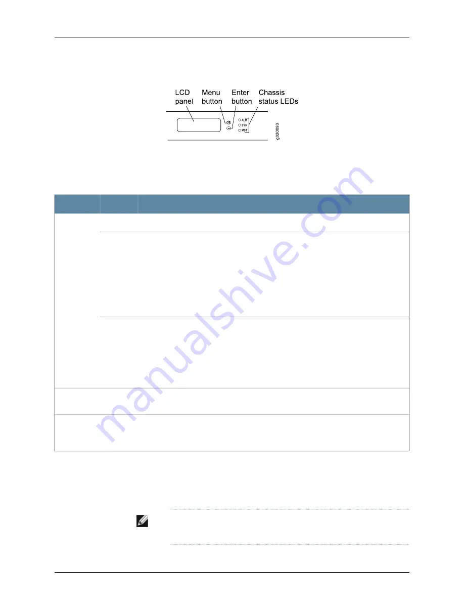
Figure 6: Chassis Status LEDs in a J-EX4200 Switch
Table 8 on page 17 describes the chassis status LEDs in a J-EX4200 switch, their colors
and states, and the status they indicate. You can view the colors of the three LEDs
remotely through the CLI by issuing the operational mode command
show chassis lcd
.
Table 8: Chassis Status LEDs in a J-EX4200 Switch
State and Description
Color
LED Label
There is no alarm.
Unlit
ALM (Alarm)
There is a major alarm.
NOTE:
When you connect power to the switch, the Alarm (ALM) LED lights red to indicate that
the network link is disconnected. This behavior is normal. Plugging an active Ethernet cable into
the management (MGMT) port on the switch completes the network link and turns off the ALM
LED. (See “Connecting a J-EX Series Switch to a Network for Out-of-Band Management” on
page 120.)
Connecting the switch to a dedicated management console instead of a network does not affect
the ALM LED. The LED remains red until the switch is connected to a network.
Red
There is a minor alarm.
NOTE:
The Alarm (ALM) LED lights amber if you commit a configuration to make it active on the
switch and do not also create a rescue configuration to back it up. To save the most recently
committed configuration as the rescue configuration, enter the operational mode command
request system configuration rescue save
. For more information, see the
Dell PowerConnect J-Series
Ethernet Switch Complete Software Guide for Junos OS
at
http://www.support.dell.com/manuals
.
Amber
•
On steadily—Junos OS for J-EX Series switches has been loaded on the switch.
•
Blinking—The switch is booting.
Green
SYS
(System)
•
On steadily—The switch is the master in the Virtual Chassis configuration.
•
Blinking—The switch is the backup in the Virtual Chassis configuration.
•
Off—The switch is a linecard member in the Virtual Chassis configuration.
Green
MST
(Master)
A major alarm (red) indicates a critical error condition that requires immediate action.
A minor alarm (amber) indicates a noncritical condition that requires monitoring or
maintenance. A minor alarm that is left unchecked might cause interruption in service or
performance degradation.
NOTE:
The amber glow of the Alarm LED that indicates a minor alarm closely
resembles the red glow that indicates a major alarm.
17
Chapter 2: Component Descriptions
Summary of Contents for PowerConnect J-EX4200
Page 6: ...vi ...
Page 12: ...xii Dell PowerConnect J Series J EX4200 Ethernet Switch Hardware Guide ...
Page 18: ...2 Dell PowerConnect J Series J EX4200 Ethernet Switch Hardware Guide ...
Page 70: ...54 Dell PowerConnect J Series J EX4200 Ethernet Switch Hardware Guide ...
Page 72: ...56 Dell PowerConnect J Series J EX4200 Ethernet Switch Hardware Guide ...
Page 78: ...62 Dell PowerConnect J Series J EX4200 Ethernet Switch Hardware Guide ...
Page 84: ...68 Dell PowerConnect J Series J EX4200 Ethernet Switch Hardware Guide ...
Page 86: ...70 Dell PowerConnect J Series J EX4200 Ethernet Switch Hardware Guide ...
Page 90: ...74 Dell PowerConnect J Series J EX4200 Ethernet Switch Hardware Guide ...
Page 100: ...84 Dell PowerConnect J Series J EX4200 Ethernet Switch Hardware Guide ...
Page 102: ...86 Dell PowerConnect J Series J EX4200 Ethernet Switch Hardware Guide ...
Page 120: ...104 Dell PowerConnect J Series J EX4200 Ethernet Switch Hardware Guide ...
Page 130: ...114 Dell PowerConnect J Series J EX4200 Ethernet Switch Hardware Guide ...
Page 152: ...136 Dell PowerConnect J Series J EX4200 Ethernet Switch Hardware Guide ...
Page 153: ...PART 4 Removing Switch Components Removing Switch Components on page 139 137 ...
Page 154: ...138 Dell PowerConnect J Series J EX4200 Ethernet Switch Hardware Guide ...
Page 167: ...PART 5 Switch and Component Maintenance Routine Maintenance on page 153 151 ...
Page 168: ...152 Dell PowerConnect J Series J EX4200 Ethernet Switch Hardware Guide ...
Page 171: ...PART 6 Troubleshooting Switch Components Troubleshooting Switch Components on page 157 155 ...
Page 172: ...156 Dell PowerConnect J Series J EX4200 Ethernet Switch Hardware Guide ...
Page 175: ...PART 7 Returning Hardware Getting Help on page 161 159 ...
Page 176: ...160 Dell PowerConnect J Series J EX4200 Ethernet Switch Hardware Guide ...
Page 186: ...170 Dell PowerConnect J Series J EX4200 Ethernet Switch Hardware Guide ...
Page 198: ...182 Dell PowerConnect J Series J EX4200 Ethernet Switch Hardware Guide ...
Page 220: ...204 Dell PowerConnect J Series J EX4200 Ethernet Switch Hardware Guide ...
Page 221: ...PART 9 Compliance Information Compliance Information on page 207 205 ...
Page 222: ...206 Dell PowerConnect J Series J EX4200 Ethernet Switch Hardware Guide ...
Page 227: ...Declarations of Conformity for J EX4200 Switches 211 Chapter 21 Compliance Information ...
Page 229: ...PART 10 Index Index on page 215 213 ...
Page 230: ...214 Dell PowerConnect J Series J EX4200 Ethernet Switch Hardware Guide ...
Page 238: ...222 Dell PowerConnect J Series J EX4200 Ethernet Switch Hardware Guide ...


