12
About Your System
Front-Panel Features and Indicators
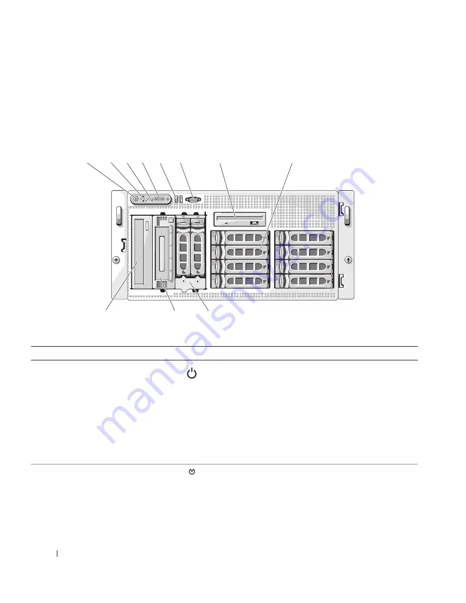
Figure 1-2 shows the controls, indicators, and connectors located behind the optional rack bezel on the
system's front panel. Table 1-2 provides component descriptions.
Figure 1-2.
Front-Panel Features and Indicators
9
10
11
7
6
1
4
2
5
8
3
Table 1-2.
Front-Panel Components
Item
Component
Icon
Description
1
Power-on indicator, power
button
The power-on indicator lights when the system power
is on.
The power button controls the DC power supply output
to the system.
NOTE:
If you turn off the system using the power button
and the system is running an ACPI-compliant operating
system, the system performs a graceful shutdown before
the power is turned off. If the system is not running an
ACPI-compliant operating system, the power is turned off
immediately after the power button is pressed.
2
NMI button
Used to troubleshoot software and device driver errors
when using certain operating systems. This button can
be pressed using the end of a paper clip.
Use this button only if directed to do so by qualified
support personnel or by the operating system's
documentation.
Summary of Contents for POWER EDGE 2900
Page 34: ...34 About Your System ...
Page 48: ...48 Using the System Setup Program ...
Page 114: ...114 Installing System Components ...
Page 138: ...138 Running the System Diagnostics ...
Page 146: ...146 Jumpers and Connectors ...
Page 176: ...176 Glossary ...
Page 182: ...82 Index 182 Index ...


