background image

4-80

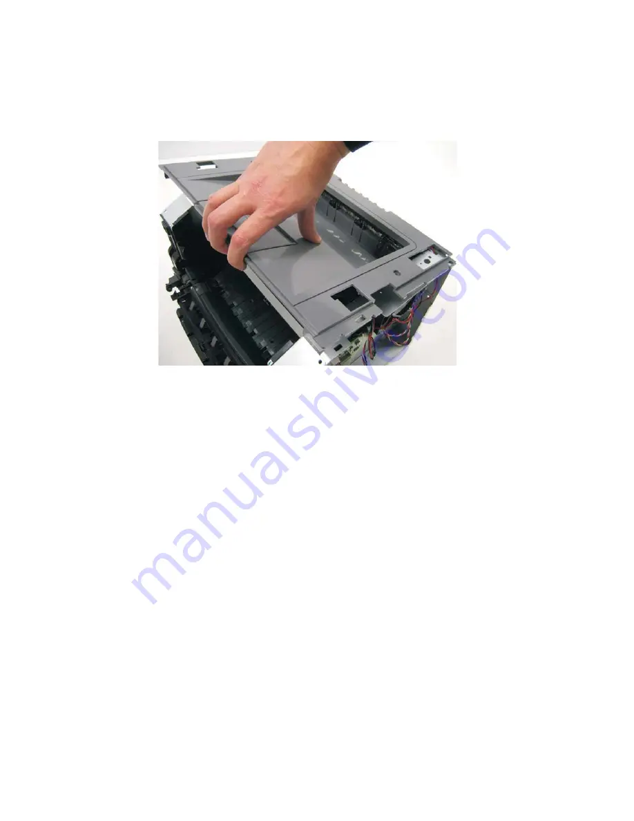
Top cover assembly removal

1.

Remove the scanner assembly. See 

“Scanner assembly removal” on page 4-88

.

2.

Lift the top cover, and remove.


Note:  

Be sure to lift the top cover assembly from the front to remove. 

During reinstallation, be sure the exit guide and the paper bin align correctly. A mismatch can cause paper 
jams.

Summary of Contents for 3333DN

Page 1: ... 02 Nov 2009 ...

Page 2: ... ...

Page 3: ...and letterhead 1 7 Storing paper 1 7 Using recycled paper and other office papers 1 7 Digital imaging specifications 1 9 General specifications 1 9 ADF Scan speed 1 9 ADF Document handling 1 9 Resolution and color depth 1 9 Flatbed document specifications 1 9 Flatbed speed 1 9 Scanner operating environments 1 9 Scan Preview 1 9 Storage environments packed 1 9 Storage environments unpacked 1 10 Til...

Page 4: ...service check 2 38 Fuser service check 2 39 LVPS HVPS service check 2 39 Main motor service check 2 40 Networking service check 2 41 Paper feed service checks 2 43 Operator panel service check 2 43 Paper jam error indication during POST 2 43 Media picks but stops halfway through the printer 2 44 Media never picks 2 44 Media occasionally mispicks or picks multiple sheets at once 2 44 Media skews 2 ...

Page 5: ...3 4 Print Quality Pages 3 4 Menu Settings Page 3 4 Event Log 3 4 Panel Menus 3 4 PPDS Emulation 3 5 Download Emuls 3 5 Factory Defaults 3 6 Energy Conserve 3 6 Min Copy Memory 3 6 Num Pad Job Assist 3 7 Format Fax Storage 3 7 Fax Storage Location 3 7 ADF Edge Erase 3 7 FB Edge Erase 3 7 Scanner Manual Registration 3 8 Disable Scanner 3 9 Paper Prompts 3 9 Envelope Prompts 3 9 Action For Prompts 3 ...

Page 6: ... 3 29 Defaults 3 29 Disk Test Clean 3 28 Printed Page Count 3 29 Permanent Page Count 3 29 Serial Number 3 29 Engine Settings 1 through 4 3 29 Model Name 3 29 Configuration ID 3 30 Edge to Edge 3 30 Enable Edge to Edge Copy 3 30 EP SETUP 3 31 EP Defaults 3 31 Fuser Temperature Fuser Temp 3 31 Fuser Page Count 3 31 Warm Up Time 3 31 Transfer 3 32 Print Contrast 3 32 Charge Roll 3 32 Gap Adjust 3 32...

Page 7: ...oller board removal 4 8 Controller board shield 4 11 Controller board cage 4 14 Controller board fan 4 14 Engine board removal 4 15 Cover open sensor 4 16 Door mount removal 4 17 Duplex removal 4 19 Duplex main motor gear drive interface removal 4 21 Fan removal 4 24 Front access door removal 4 25 Fuser removal 4 28 Scanner front cover removal 4 31 Left side cover removal 4 33 Front door access co...

Page 8: ...85 Flatbed removal 4 86 Scanner assembly removal 4 88 ADF separator pad 4 95 ADF separator roll assembly 4 96 Kickstand removal 4 97 Output bin LED and lens removal 4 98 ADF cable removal 4 99 Left scanner cover removal 4 100 Right scanner cover removal 4 101 Option board installs and removals 4 102 Lifting the Scanner to the up position 4 102 Installing an Internal Solutions Port ISP 4 103 Printe...

Page 9: ...le of contents ix Assembly 2 Imaging 7 4 Assembly 3 Tray assemblies 7 6 Assembly 4 Electronics 7 8 Assembly 5 Frame 7 10 Assembly 6 Options 7 12 Assembly 7 Power cords 7 13 Index I 1 Part number index I 5 ...

Page 10: ...x Service Manual ...

Page 11: ...ordnungsgemäßer Wartung durch den Kundendienst Laserbestrahlung die Klasse I übersteigen würde Menschen keinesfalls erreicht Avis relatif à l utilisation de laser Pour les Etats Unis cette imprimante est certifiée conforme aux provisions DHHS 21 CFR alinéa J concernant les produits laser de Classe I 1 Pour les autres pays cette imprimante répond aux normes IEC 60825 1 relatives aux produits laser ...

Page 12: ...ssio de 7 milliwatts operando numa faixa de comprimento de onda entre 655 e 675 nanómetros O sistema e a impressora laser foram concebidos de forma a nunca existir qualquer possiblidade de acesso humano a radiação laser superior a um nível de Classe I durante a operação normal a manutenção feita pelo utilizador ou condições de assistência prescritas Laserinformatie De printer voldoet aan de eisen ...

Page 13: ...aessa olet alttiina näkymättömälle lasersäteilylle Älä katso säteeseen VARNING Osynlig laserstrålning när denna del är öppnad och spärren är urkopplad Betrakta ej strålen Laser notis Denna skrivare är i USA certifierad att motsvara kraven i DHHS 21 CFR underparagraf J för laserprodukter av Klass I 1 I andra länder uppfyller skrivaren kraven för laserprodukter av Klass I enligt kraven i IEC 60825 1...

Page 14: ...5 1 Els productes làser de classe I no es consideren perillosos Aquesta impressora conté un làser de classe IIIb 3b d arseniür de gal li nominalment de 7 mil liwats i funciona a la regió de longitud d ona de 655 675 nanòmetres El sistema làser i la impressora han sigut concebuts de manera que mai hi hagi exposició a la radiació làser per sobre d un nivell de classe I durant una operació normal dur...

Page 15: ...Notices and safety information xv ...

Page 16: ...xvi Service Manual ...

Page 17: ...n de ce produit pouvant présenter certains risques électriques le personnel d entretien qualifié devra prendre toutes les précautions nécessaires ATTENTION Ce symbole indique la présence d une tension dangereuse dans la partie du produit sur laquelle vous travaillez Débranchez le produit avant de commencer ou faites preuve de vigilance si l exécution de la tâche exige que le produit reste sous ten...

Page 18: ...te producto está dirigida exclusivamente al personal cualificado de mantenimiento Existe mayor riesgo de descarga eléctrica y de daños personales durante el desmontaje y la reparación de la máquina El personal cualificado debe ser consciente de este peligro y tomar las precauciones necesarias PRECAUCIÓN este símbolo indica que el voltaje de la parte del equipo con la que está trabajando es peligro...

Page 19: ...ent a professionals i no està destinada a ningú que no ho sigui El risc de xoc elèctric i de danys personals pot augmentar durant el procés de desmuntatge i de servei d aquest producte El personal professional ha d estar ne assabentat i prendre les mesures convenients PRECAUCIÓ aquest símbol indica que el voltatge de la part de l equip amb la qual esteu treballant és perillós Abans de començar des...

Page 20: ...ions uses illustrations to identify the connector locations and test points on the printer 6 Preventive maintenance contains the lubrication specifications and recommendations to prevent problems 7 Parts catalog contains illustrations and part numbers for individual FRUs Conventions Note A note provides additional information Warning A warning identifies something that might damage the product har...

Page 21: ...ptom and repair the failure See Diagnostics information on page 2 1 for more information See Repair information on page 4 1 to help identify parts After completing the repair perform tests as needed to verify the repair small workgroups The 3333dn 3335dn MFPs allow users to print copy scan and fax documents This book contains information on the 3333dn 3335dn MFPs The Dell 3333dn 3335dnMFPs are mon...

Page 22: ...ots ISP INA slot 1 1 Memory slots 1 1 Flash memory option card 2 2 Both slots are active for either a 256MB Flash memory card a font card or a DLE Multiple Flash font or DLE cards are not supported Item Print resolution 1200 Image quality 2400 Image quality 600 X 600 dpi 1200 X 1200 dpi 1200 Image quality is defined as 600 dpi with 2 bit IET Image Technology default mode for all models 2400 Image ...

Page 23: ... Host based printing PCL 5e and PCL 6 PostScript 3 PPDS migration tool PDF v1 6 XPS HTML including DBCS Direct image Compatibility Windows Macintosh Linux Windows Macintosh Linux Standard local connections USB Standard network connections Ethernet 10 100 Base Tx Wireless ethernet 802 11b g n x Optional local connections Optional network connections external print server support All models are USB ...

Page 24: ...vailable output trays Standard 150 sheet sensing bin Toner and photoconductor Toner cartridge 7 000 standard pages SWE 3 500 standard pages 7 000 standard pages SWE 3 500 standard pages High toner cartridge 9 000 standard pages 9 000 standard pages Extra high yield 15 000 standard pages 15 000 standard pages Photoconductor kit Up to 30 000 Up to 30 000 Declared value in accordance with ISO IEC 197...

Page 25: ...olio statement Plain paper transparency recycled labels bond letterhead preprinted colored paper light paper heavy paper rough cotton custom type x 60 163 g m 16 43 lb 50 paper 15 labels 10 transparencies Card stock 120 163 g m 16 43 lb Index Bristol 75 163 g m 46 100 lb Tag 20 7 9 10 DL C5 B5 other Envelopes Rough envelopes 75 g m 20 lb 7 Duplex A4 letter legal oficio Mexico folio Plain paper rec...

Page 26: ...n its original wrapper until it is time to use it This limits the exposure of paper to moisture changes that can degrade its performance Condition paper before printing by storing it in its original wrapper in the same environment as the printer for 24 to 48 hours before printing Extend the time several days if the storage or transportation environment is very different from the printer environmen...

Page 27: ...ams and uneven print quality For best results store paper where the temperature is 21 C 70 F and the relative humidity is 40 Most label manufacturers recommend printing in a temperature range of 18 to 24 C 65 to 75 F with relative humidity between 40 and 60 Store paper in cartons when possible on a pallet or shelf rather than on the floor Store individual packages on a flat surface Do not store an...

Page 28: ...1 8 Service Manual ...

Page 29: ...table through electronics Color depth 48 bit RGB output 16 bit channel Mono ADF optical resolution Max 600 x 600 dpi Color ADF resolution Max 600 x 300 dpi final resolution of 300 x 300 dpi Flatbed document specifications Flatbed scan area Max 8 5 x 14 216mm x 355 6mm Document size Up to A4 and legal 4 5 x 5 5 to 8 5 x14 SEF Flatbed speed 3 seconds to scan 3 seconds to return Scanner operating env...

Page 30: ...e output formats TIFF JPEG PDF and secure PDF XPS Supported compressions PDF 1 bit JBIG2 CCIT G4 Flate 8 24 bit Flate JPEG TIFF 1 bit CCITT G4 8 24 bit Packbits LZW JPG 8 24 bit JPG Supported scan destinations Temporary profile from a user s PC FTP Scan to PC via network TWAIN Scan to PC using Web applet Scan to E Mail Scan to USB Windows network folder requires installing embedded scan to folder ...

Page 31: ...General information 1 11 Reduce Enlarge 25 to 400 Copy only ...

Page 32: ...Detection 16dBm 59dBm Complies with all regulatory requirements Receive 200x100 dpi 200x200 dpi 300x300 dpi 400x400 dpi 204x98 dpi 204x196 dpi 204x391 dpi 408x391 dpi Send 200x100dpi 200x200 dpi 300x300 dpi Fax memory 4 MB Flash More than 320 pages based on ITU chart 1 User selectable parameters are stored in NVRAM Speed dial Non hard drive model 500 Hard drive 1800 Transmission Approximately 3 se...

Page 33: ...eneral information 1 13 Tools The removal and adjustment procedures require the following tools and equipment Spring hook Needle nose pliers Volt ohmmeter 1 and 2 Phillips screwdriver Slotted screwdriver ...

Page 34: ... Direct Current DIMM Dual Inline Memory Module DLE Downloadable emulator DRAM Dynamic random access memory DVM Digital multimeter ECC Error correcting code ECM Error correction mode EDO Enhanced Data Out EEPROM Electrical Erasable Programmable Read Only Memory ENA External Network Adapter EOL End of line EP Electrophotographic process EPROM Erasable programmable read only memory ESD Electrostatic ...

Page 35: ...itch NAND NAND usage NAND gate NVM Nonvolatile Memory NVRAM Nonvolatile Random Access Memory OCF Operator correctable failure OEM Original Equipment Manufacturer OHP Overhead projector OPC Optical photo conductor OPT Optical Sensor PC Photoconductor PDF Portable Document Format PICS Problem isolation charts PIN Personal identification number PIXEL Picture element PJL Printer Job Language POR Power...

Page 36: ...Memory Module SOL Solenoid SOS Start of scan SRAM Static random access memory TAR Toner Add Roll TPS Toner Patch Sensing TTM Tandem Tray Module TVOC Total Volatile Organic Compound UAT Universally Adjustable Tray UPR Used Parts Return USB Universal Serial Bus V Volts V ac Volts alternating current V dc Volts direct current VOIP Voice over internet protocol VOM Volt Ohmmeter VTB Vacuum Transport Be...

Page 37: ...es User status messages provide the user with information on the current status of the printer Ready displays on the first line of the display unless invoked and then Power Saver displays If a user status message is displayed then go to Service error codes on page 2 26 User attendance messages are indicated by a two or three digit error code that provides the user with information that explains a ...

Page 38: ...erlock switch service check on page 2 37 POST completes but the display does not come on See Operator panel service check on page 2 43 Main motor does not come on See Main motor service check on page 2 40 Fan does not come on See Cooling fan service check on page 2 37 Fuser does not cycle See Fuser service check on page 2 39 Fuser does not turn on and off See Fuser service check on page 2 39 The p...

Page 39: ...r interlock switch service check on page 2 37 Operator panel button not responding See Operator panel service check on page 2 43 Operator panel lights are off or very dim See Operator panel service check on page 2 43 Blank page See Blank page on page 2 47 Black page See Black page on page 2 48 Heavy background See Heavy background on page 2 48 Light print See Light print on page 2 50 White or blac...

Page 40: ...o to Black or blank page copy service check on page 2 57 Black page No dial tone Go to Modem fax card service check on page 2 63 Machine dials a number but fails to make a connection with another fax machine The other fax machine may be turned off Ask the fax recipient to check their machine Incoming fax has blank spaces or poor quality 1 The sending fax machine may be faulty 2 The sending fax mac...

Page 41: ...ons When outside of the Fax menu fax function or home screen pressing causes an error beep 4 Back In the Copy menu press to delete the right most digit of the value in the Copy Count The default value of 1 appears if the entire number is deleted by pressing numerous times In the Fax Destination List press to delete the right most digit of a number entered manually You can also press to delete an e...

Page 42: ...gs If pressed while a job is scanning the button has no effect 7 Indicator light Indicates the printer status Off The power is off Blinking green The printer is warming up processing data or printing Solid green The printer is on but idle Blinking red Operator intervention is needed 8 Stop Stops all printer activity A list of options is offered once Stopped appears on the display Item Description ...

Page 43: ...s Ready or Busy Shows printer conditions such as Toner Low Shows intervention messages to give instructions on what you should do so the printer can continue processing such as Close door or Insert print cartridge 6 Status Supplies Appears on the display whenever the printer status includes a message requiring intervention Touch it to access the messages screen for more information on the message ...

Page 44: ...le it appears Touching this button opens a PIN entry screen Entering the correct PIN unlocks the printer control panel touch screen and hard buttons Cancel Jobs Opens the Cancel Jobs screen The Cancel Jobs screen shows three headings Print Fax and Network The following items are available under the Print Fax and Network headings Print job Copy job Fax profile FTP E mail send Each heading has a lis...

Page 45: ...up your screens and buttons may vary from those shown Sample touch screen Button Function Home Returns to the home screen Scroll down Opens a drop down list Left scroll decrease Scrolls to another value in decreasing order Right scroll increase Scrolls to another value in increasing order Left arrow Scrolls left ...

Page 46: ...o the previous screen Button Function Down arrow Moves down to the next screen Up arrow Moves up to the next screen Unselected radio button This is an unselected radio button The radio button is gray to show it is unselected Selected radio button This is a selected radio button The radio button is blue to show it is selected Button Function Submit ...

Page 47: ... a column under it which can show only three jobs per screen Each job appears as a button which you can touch to access information about the job If more than three jobs exist in a column then an arrow appears enabling you to scroll through the jobs Continue Touch this button when more changes need to be made for a job or after clearing a paper jam Cancel Cancels an action or a selection Cancels o...

Page 48: ...niversal Setup Option Card Menu Print PS Error Font Priority Reports Menu Settings Page Device Stats Network Setup Shortcuts Fax Job Log Fax Call Log Copy Shortcuts E Mail Shortcuts Fax Shortcuts FTP Shortcuts Profiles Setup List Print Fonts Print Directory Demo Asset Report Network Ports Active NIC Standard Network SMTP Setup Standard USB Security Edit Security Setup Misc Settings Confidential Pr...

Page 49: ...LL in the Web Link Setup The system administrator needs to configure the server SMTP server not setup Contact system administrator The devices primary and secondary SMTP fields are blank This needs to be configured by the system administrator No Analog Phone Line An analog line is not detected as being plugged into the modem If the device is in Analog mode this has a source of Fax If the device is...

Page 50: ...ct media meeting the description custom type in source where source is Tray 1 or Tray 2 Load the input source with the correct type and size media Cancel the current job Load source size Printer does not detect media meeting the size requested in the source indicated Load the input source with the correct type and size media Cancel the current job Load source type size Printer does not detect medi...

Page 51: ...e jobs available Jobs may also be restored at a later time by turning off and restarting the printer The following actions can be taken Restore Do not restore More information Securely Clearing Disk Space This message appears when all blocks of the disk are cleared Unsupported USB Device Please Remove Remove the unrecognized device from the USB port on the front of the printer Unsupported USB Hub ...

Page 52: ...t job The following actions can be taken press Select to print the portion of the job already stored and begin collating the rest of the job press Menus to access the Busy Waiting Menu The following functions are available Cancel Job Note Menu Lockout does NOT prevent access to the Busy Waiting Menu 37 Insufficient memory for flash defragment operation This message is displayed when insufficient p...

Page 53: ...stored on the flash memory Install a larger capacity flash memory card 53 Unformatted Flash press Select to clear the message and continue printing You must format the flash memory before you can store any resources on it If the error message remains the flash memory may be defective and require replacing 54 Standard Network Software Error This message is displayed when the RIP software detects th...

Page 54: ...vice to satisfy a Check Device Connections reattach message the user should reinstall an associated compatible option or hot unplug the option 1 Turn off and unplug the printer 2 Remove the incompatible trays 3 Plug in the printer and turn it on 61 Defective Disk This error code displays when the printer detects a defective disk This error may occur at power on or during disk format and write oper...

Page 55: ...or the correct DLE version Scanner ADF cover open The cover to the ADF is open Close the ADF cover If this doesn t remedy the problem Go to ADF cover open service check on page 2 59 Scan job too long The scan job exceeds the maximum number of pages Break the scan job into multiple small jobs Cancel the scan job Scan Paper cleared Paper is cleared from ADF Cancel job Restart job This can only be pe...

Page 56: ...a at the input sensor before interrupt occurred not enough time elapsed since the printhead started to expect the printhead mirror motor lock Possible causes include bouncy sensor or exceptionally fast pick perhaps due to media pre staged in the source tray Carefully remove the tray and notice if the leading edge of the media is pointed upward and out of the tray If so then inspect the tray wear s...

Page 57: ... path Check the bottom of the PC kit for any obstructions Remove the upper front guide and inspect the pinch rollers 200 20 The media is too long over the manual feeder sensor Possible causes include multi sheet feed media size length problem pre staged media in the tray Verify that the media is approved Inspect the wear strips in the tray and replace if they are worn 200 22 FAILED SMALL GAP OR NO...

Page 58: ...t sensor while waiting for any page s ahead to clear the paper path Possible cause is that the page is delayed at the alignment gate 200 35 Failed to create hsync during auto alignment Check the printhead See Printhead service check on page 2 54 200 36 Lost hsyncs during auto alignment 200 37 Timeout on data collection during auto alignment 200 38 Interpage servo gap is smaller than expected for p...

Page 59: ...door and inspect the flag on the exit sensor The flag is located behind the fuser exit rollers about mid printer If the flag does not rotate freely or has no spring action then replace the fuser See Fuser removal on page 4 28 202 02 Exit sensor never broke from sheet ahead of page heading toward the exit sensor 202 06 Exit sensor bounced 202 13 Exit sensor covered media not expected media not in m...

Page 60: ...media was in the source while other sheets were committed to the paper path Remove the tray and inspect the media path for obstructions Check the pick rollers Replace the pick rollers if they are worn or clogged with dust See ACM pick tire roller removal on page 4 3 Also check the wear strips and the manual feeder and replace if necessary 241 16 Failed to feed from tray 1 Pages in the paper path h...

Page 61: ...irst scanner sensor while the ADF is in an idle state Remove all paper from the ADF Retry the job If the error recurs Go to ADF paper jam service check on page 2 60 291 00 Scanner Static Jam 2nd scanner sensor Scanner ADF detects paper at the second scanner sensor while the ADF is in an idle state 292 Scanner jam remove all originals from the scanner This message appears if the ADF cover is open w...

Page 62: ...nner Failure ADF mechanical failure Go to ADF paper jam service check on page 2 60 843 02 Scanner Failure General mechanical failure 843 03 Scanner Failure Pick Roller engage failure 843 04 Scanner Failure Pick roller disengage failure 844 yy Scanner Failure Lamp failure Go to CCD service check on page 2 57 844 Front scan module output level error Go to CCD service check on page 2 57 844 01 Rear s...

Page 63: ...p has excessive bow 846 06 Front calibration strip has excessive dark area Front excessive variability for Mono Red Green or Blue Go to CCD service check on page 2 57 846 07 Front magnification exceeds limits Rear excessive variability for Mono Red Green or Blue Go to CCD service check on page 2 57 847 Modem Failure The Configuration ID bit that describes the device s modem doesn t match the actua...

Page 64: ...x DC pick motor over speed 914 00 DC pick motor error 914 01 Lost encoder feedback Transfer service errors 917 xx Transfer service error Replace the transfer roll See Transfer roll service check on page 2 54 Fuser service errors 920 00 Under temperature during steady state control Replace the fuser See Fuser service check on page 2 39 921 00 Under temperature during standby control 922 00 Fuser fa...

Page 65: ...in motor service check on page 2 40 Power supply service errors 940 00 LVPS service error Replace the LVPS HVPS See LVPS HVPS service check on page 2 39 Controller board and operator panel service errors 948 xx Failed engine board Replace the controller board See Engine board service check on page 2 36 949 xx 950 xx Mismatch between EEPROM and mirror memory Note A new controller board or operator ...

Page 66: ...nd call the next level of support or replace the controller board See Controller board service check on page 2 35 959 20 Controller hardware failure Replace the controller board See Controller board service check on page 2 35 959 21 Code did not respond to command request 959 22 Challenge secret failure 959 23 Self test failed during initialization Replace the controller board See Controller board...

Page 67: ...e specified device but the device is unable to identify the exact component failure 991 xx The specified device has detected an equipment check in its system card Fax error log codes Error code Description Action 000 No error occurred during fax transmission No action needed 200 Error occurred when transmitting training Check line quality Select a lower Max Speed value under Fax Send settings Adju...

Page 68: ...ion Adjust Transmit Level Receive Threshold values 80A T5 Timeout occurred when transmitting image data to remote fax device Check line quality Adjust Transmit Level Select a lower Max Speed value under Fax Send settings 80B Too many errors when transmitting in ECM mode Check line quality Adjust Transmit Level Select a lower Max Speed value under Fax Send settings 80C Remote device failed to respo...

Page 69: ...7 terminal modulation schemes Select a lower Max Speed under Fax Send settings Adjust the Transmit Level Check line quality 882 Failure to transmit training successfully in V17 V29 terminal modulation schemes Select a lower Max Speed under Fax Send settings Adjust the Transmit Level Check line quality 883 Failure to transmit training successfully in V17 V27 terminal modulation schemes Select a low...

Page 70: ...dem fax card service check on page 2 63 905 A timeout occurred after dialing the number and waiting for a response Check with remote end if successive attempts fail 906 Fax cancelled by user No action needed 907 Modem detected a digital line connection Verify the MFP is connected to an analog line See Fax transmission service check on page 2 64 908 Phone line was disconnected Restore phone line co...

Page 71: ...er board 4 Cables are plugged in correctly especially for the operator panel The printer will not power up without a functioning operator panel 5 The operator panel See Operator panel service check on page 2 43 Verify 24 V dc and 5V dc input from the engine board 1 Turn the printer off 2 Disconnect the controller board power cable from the engine board at J503 3 Turn the printer on 4 Verify 24 V d...

Page 72: ... card connector are grounded 7 If grounds are not correct on the cable but the cable passes continuity otherwise then check the LVPS HVPS 8 If the grounds are not correct on the engine board then replace the engine board Check with one probe on the connector pin and the other on the card s ground plane found at each screw head Engine board voltage outputs Turn the printer off and plug the LVPS HVP...

Page 73: ... Make sure the fan cable plug is properly seated at J36 engine board Turn the printer on Within a few seconds the engine board assembly should apply 24 V dc to pin 2 If voltage is not present then check or replace the engine board See Engine board removal on page 2 15 If voltage is present then check pin 1 for 24 V dc as well If it is close to 24 V dc while the fan is still idle then replace the f...

Page 74: ...ck the switch continuity across its conductors with the switch on Turn the switch off Plug the AC line into the LVPS HVPS and switch unit on Note Voltages are exposed at several places on the board Do these verifications and then unplug the AC cord from the power supply If voltages are not correct then replace the LVPS HVPS If voltages are correct then check the engine board See Engine board servi...

Page 75: ...essary If the cable tests good then replace the fuser Reconnect the cables turn the printer on and at 12 check for approximately 5 V dc on pin 1 and ground on pin 2 If line voltage is incorrect on pin 1 then see Engine board service check on page 2 36 for more information Fuser Disconnect the thermistor cable from J12 on the engine board Measure the resistance across the ends of the thermistor cab...

Page 76: ...nter and check for the following voltages at J17 Verify ground at pin 5 for both the card and cable If these voltages are correct then check the main motor cable for continuity Remove the left side cover to access the connector on the motor If continuity exists on each wire then replace the main motor gear drive which includes the motor If continuity does not exist on one or more of the wires then...

Page 77: ...nd in a Ready state Go to step 5 Go to step 4 4 Change the printer status to online Did this fix the issue Problem resolved Go to step 5 5 Does the IP address displayed on the network settings page match the IP address in the port of the drivers using the printer Go to step 10 Go to step 6 6 Does the LAN use DHCP Note A printer should use a static IP address on a network Go to step 7 Go to step 9 ...

Page 78: ...ommunicating properly Go to step 18 Contact the network administrator 18 Verify that the ISP wireless card cable and any other ISP cables are properly seated in their connectors Are the cables connected correctly Go to step 20 Go to step 19 19 Properly reseat the ISP cables Did this fix the problem Problem resolved Go to step 20 20 Perform the option card service check See Option card service chec...

Page 79: ...en see Controller board service check on page 2 35 If these are approximately correct and the operator panel is not functioning 1 Turn the printer off 2 Remove the left and right covers 3 Tilt the operator panel keyboard and verify the UICC cable is properly connected to the keyboard at connector J10 4 If the cable is properly connected at both ends check the cable for continuity If the cable fail...

Page 80: ... If correct then replace the input paper feed sensor If these voltages are not correct then replace the controller board Check the pick tires Clean or replace as necessary FRU Action Paper feed pick tires tray 1 Paper feed pick tires tray 2 Media drive ASM Media feed clutch ASM Manual feed clutch ASM P U and manual feed solenoid ACM drive shaft Open the left cover and verify that the solenoids and...

Page 81: ... engine board as necessary FRU Action Paper feed pick tires tray 1 Paper feed pick tires tray 2 Tray 1 Tray 2 option Check tires for debris If tires are new then try reversing each on its hub Check side guides on Tray 1 and Tray 2 Guides set for a full stack of media may be too wide when the stack is short FRU Action Fuser This problem is most likely due to a worn backup roll It causes the printer...

Page 82: ...tion cable Warning Do not replace the engine board and controller board at the same time Each board contains the printer settings When either of these boards is new it obtains the settings from the other board Settings are lost when both are new and replaced at the same time Card Remove all the option cards from the device Install each card individually Restart the MFP after each card is installed...

Page 83: ...reen The machine will POR Note Refer to the print defects guide at the end of the manual for repeating defects Blank page FRU Action Toner cartridge not a FRU Remove the toner cartridge and gently shake it to evenly distribute the toner Check for cartridge damage Printhead LVPS HVPS Controller board Blank pages can be caused by a defective printhead assembly LVPS HVPS or controller board Printhead...

Page 84: ... 11 13 and 15 Verify ground on pins 10 12 14 16 and 18 If any of the values are incorrect then replace LVPS HVPS board If the grounds are incorrect then check ground paths Check continuity in the cable If the cable is bad then call the next level of support If the values are correct and the toner electrodes are good then replace the controller board See the LVPS HVPS service check on page 2 39 and...

Page 85: ...rum Try a new PC Kit Transfer roll Note Do not touch the transfer roll except at its ends Place a sheet of paper over the roll to prevent damage from finger oils or hand lotion Check the springs in the left and right transfer roll bearings The bearing assemblies should support the transfer roll applying evenly distributed forces to the PC drum Replace the transfer roll assembly if the springs or b...

Page 86: ...ion in the speed of the media as it feeds through the printer especially in the developer and transfer process It may also be a result of overly dry or moist environments With the printer off check to make sure that the laser beam is not blocked Inspect the toner cartridge and paper feed components especially the drive coupler and drive gears for debris binds or damage FRU Action Photoconductor ki...

Page 87: ... With the printer off clear the path or clean the lens The toner cartridge or fuser may be defective Try a different toner cartridge Inspect the fuser at its entry for debris Toner smudges appear on the front or back of the page Make sure the media is straight and unwrinkled Replace the PC Kit and recheck before replacing the toner cartridge See Toner on back of page on page 2 50 for more informat...

Page 88: ...ner Replace the toner cartridge Solid black areas on transparencies There is a mismatch in the transparency and what the software is expecting Choose a different fill pattern in the software program Remove the toner cartridge and gently shake it from side to side to redistribute the toner Try a different type of transparency Replace the toner cartridge Faint images or repetitive spots appear on th...

Page 89: ...le sheets The friction between sheets is too high Remove the media from Tray 1 or Tray 2 and fan it Don t overfill Tray 1 or the optional Tray 2 see media capacities in the media types and sizes chart in the User s Reference The media fails to feed from Tray 1 Frictional force between tires and media is less than resisting force Remove the media from Tray 1 and fan it Make sure Tray 1 is selected ...

Page 90: ...nter off Disconnect the printhead cables from J9 and J6 on the controller board Turn the printer on with the front door closed On the controller board verify 5 V dc on pins 2 and 3 at J6 and 5 V dc on pins 1 and 10 at J9 Verify grounds on pins 4 5 6 and 7 at J6 and on pin 4 at J9 If voltages or grounds are incorrect then check the controller board See Controller board service check on page 2 35 fo...

Page 91: ... error recur Go to step 2 Stop Problem resolved 2 Re enter Configuration mode scroll to and select the Disable Scanner menu item Does the screen display ADF Disabled or Auto Disabled Go to step 3 Go to step 8 3 Check the ADF cable connections on the ADF relay card and connector J17 on the controller board Also inspect the cable connections on J28 J12 13 and J30 on the controller board Are the conn...

Page 92: ...ating mode Run a copy from the ADF Did the 840 xx error recur Go to step 8 Stop Problem solved 8 Inspect J17 J12 13 and J30 on the controller board Are the connections properly connected Go to step 10 Go to step 9 9 Properly connect all the connections Did the 840 xx error recur Go to step 10 Stop Problem solved 10 Replace the flatbed unit See Flatbed removal on page 4 53 POR the machine into conf...

Page 93: ...roller board removal on page 4 16 Step Questions actions Yes No 1 Restart the device and retry the scan copy job Repeat this step with a few copy jobs Does the error return Go to step 2 No issue 2 Is the CCD ribbon cable properly connected to J30 on the controller board Go to step 3 Properly connect the ribbon cable to J30 3 Replace the flatbed unit See Flatbed removal on page 4 53 Did this resolv...

Page 94: ...he cable 4 Check pin 1 in J28 for voltage The voltage is only present when a flatbed copy job is running The voltage should measure 24V AC Is voltage present Go to step 5 Replace the controller board Go to Controller board removal on page 4 16 5 Ensure that the home position cable J13 is connected Is the cable connected Go to step 6 Properly connect the cable 6 Check pin 1 in J13 for voltage The v...

Page 95: ... ADF rear cover and clean the dirt and debris from the sensor Does this fix the issue Issue resolved Go to step 8 8 Inspect the connections on the ADF relay card in the ADF Are all the connections properly connected Go to step 9 Secure all the connections 9 Check the ADF cable for continuity Is there continuity Go to step 10 Replace the ADF cable See ADF cable removal on page 4 99 10 Check for sig...

Page 96: ...canner Tests on page 3 25 Are the sensors working properly Go to step 6 Go to step 9 6 Check the leading edge of the paper to ensure the paper is not curled or bent in a way that would keep it from contacting the paper present sensor actuator Is the paper damaged Bad media Go to step 7 7 Is there dirt in the sensors or is the paper present actuator stuck Clean the sensors or remove debris from the...

Page 97: ...he ADF Go to step 5 There is no issue 5 Is the leading edge of the paper wrinkled or torn Use different media Go to step 6 6 Perform the ADF paper present sensor test Go to Scanner Tests on page 3 25 Is the sensor working properly Go to step 7 Properly connect all the connections in the ADF relay card 7 Check the actuators to see if they are jammed or damaged Are they jammed or damaged Replace the...

Page 98: ...ons on the ADF relay card Are they properly connected Go to step 4 Properly connect all the connections 4 Check the ADF cable to ensure it is properly connected to CN 15 on the ADF relay card and main controller board at J17 Is the ADF cable properly connected Go to step 5 Properly connect the ADF cable to its connections 5 Check the ADF cable for continuity Make sure pin 22 has continuity Is ther...

Page 99: ...fix the problem Problem resolved Go to step 5 5 Is the modem card cable properly connected to the system board at J8 and the modem card Go to step 7 Go to step 6 6 Properly connect the modem card cable to the modem card and system board Did this fix the problem Problem resolved Go to step 7 7 Check the modem card cable for continuity Is there continuity Go to step 8 Replace the modem card cable 8 ...

Page 100: ...Go to step 6 6 Is the line being used a VOIP line Go to step 7 Go to step 8 7 Have the system administrator verify that the VOIP server is configured to receive faxes Is the server properly configured Go to step 8 Stop here The issue is VOIP related The VOIP provider needs to change the server configuration 8 Is the MFP on a PABX Go to step 9 Go to step 10 9 Enable Behind a PABX under fax settings...

Page 101: ...it Level setting in steps of 1db For example if default value is 11 db changing it to 12db will decrease the signal strength by 1db and changing it to 10db will increase the signal strength by 1db Recommended adjustment range is 5 db in 1db steps from the default value Did this fix the problem Stop Problem resolved Go to your second level of support See Escalating a fax issue to second level suppo...

Page 102: ... the Enable Fax Receive setting is on Is the setting set to on Go to step 9 Go to step 8 8 Set Enable Fax Receive to On Did this fix the problem Problem resolved Go to step 9 9 Is Distinctive Ring enabled Go to step 11 Go to step 10 10 Turn on Distinctive ring Did this fix the problem Problem resolved Go to step 11 11 Is the phone line analog Go to step 13 Go to step 12 12 Is the VOIP server confi...

Page 103: ...level by decreasing increasing the Receive Threshold setting in steps of 2db For example if default value is 43 db changing it to 45db will decrease the received signal level by 2db and changing it to 41db will increase the received signal level by 2db Recommended adjustment range is between 33db and 48db in 2db steps Did this fix the problem Problem resolved Go to step 20 20 Press 411 to enter th...

Page 104: ...requested information This is where you will type in the information you retrieved in step 3 Second level support can assist you if you have questions about the information requested on the page Note The fields requesting the code levels model number type of problem are auto filled If the information is not in the fields it can be retrieved from the SE menu The SE menu can be accessed by pressing ...

Page 105: ... mode to test the repair Configuration Menu 1 Turn off the printer 2 Press and hold 2 and 6 3 Turn on the printer 4 Release the buttons after 10 seconds The Configuration Menu group contains a set of menus settings and operations which are infrequently required by a user Generally the options made available in this menu group are used to configure a printer for operation See Configuration menu CON...

Page 106: ...ax Storage See Format Fax Storage on page 3 7 Fax Storage Location See Fax Storage Location on page 3 7 ADF Edge Erase See ADF Edge Erase on page 3 7 FB Edge Erase See FB Edge Erase on page 3 7 Scanner Manual Registration See Scanner Manual Registration on page 3 8 Disable Scanner See Disable Scanner on page 3 9 Paper Prompts See Paper Prompts on page 3 9 Envelope Prompts See Envelope Prompts on p...

Page 107: ...he device To view the Maintenance Counter Value touch Maintenance Counter Value from the Configuration Menu The panel displays the current value of the maintenance counter as illustrated below Touch Back to return to the Configuration Menu After installing the required maintenance kit reset this count to zero Reset Maintenance Counter After scheduled maintenance reset the Maintenance Counter To re...

Page 108: ...uch Print Quality Pages from the Configuration Menu Printing Quality Test Pages appears on the LCD Touch Back to return to the Configuration Menu The Reports menu contains two selections Menu Settings Page and Event Log Menu Settings Page To print the Menu Settings page press Press to return to the Configuration menu Event Log The event log provides a history of printer errors The event log can on...

Page 109: ...urrent value appears on the touch screen 2 Touch or to scroll through the setting s possible values 3 Touch Back to cancel and return to the Configuration Menu 4 Touch Submit to save the change Download Emuls This setting enables you to disable a Downloadable emulator DLE that is installed on the MFP The setting for this menu setting is disabled Note The DLE is re enabled automatically after two P...

Page 110: ...gy Conserve menu then Disabled appears in the Power Saver menu and Power Saver can be turned off If On is set in the Energy Conserve menu the Power Saver feature cannot be disabled To change this setting 1 Touch Energy Conserve from the Configuration Menu setting s current value appears on the touch screen 2 Touch or to scroll through the setting s possible values 3 Touch Back to cancel and return...

Page 111: ... Fax Flash DO NOT POWER OFF appears on the LCD while the format operation is active Fax Storage Location To change this setting 1 Touch Fax Storage Location from the Configuration Menu setting s current value appears on the touch screen 2 Touch or The settings are Disk and NAND 3 Touch Submit to save the change ADF Edge Erase This menu item sets the size in millimeters of the no print area around ...

Page 112: ...rify the changes by placing the print quick test page face up and touching Copy Quick Test 10 Repeat steps 6 7 and 8 as needed 11 To view and adjust the duplex ADF backside registration place the quick test page face down up into the ADF and touch Copy Quick Test 12 After the quick test page copies touch ADF Back 13 Use the or to increase or decrease the settings value for horizontal adjust and to...

Page 113: ...alues 3 To exit this screen without changing the setting s value touch Back 4 To save the setting s new value touch Submit Envelope Prompts This setting controls the tray the user is directed to refill when a specific envelope size is out The selections are Auto default MP Feeder and Manual Env To change the value of this setting 1 Touch Env Prompts from the Configuration Menu setting s current va...

Page 114: ...Touch Disk Encryption from the Configuration Menu Note If an advanced password has been established you must enter this password in order to change the setting If no advanced password exists you can establish one by using the keyboard that appears on the LCD 2 Touch Submit to save the change 3 Touch Back to cancel and return to the Configuration Menu If you remove an encrypted disk from a device a...

Page 115: ...ss indicators during the two stage process 1 2 indicates that the process is currently in the first stage 0 indicates the progress of the current stage of the process The progress bar indicates the overall completion of the entire process by filling in throughout each separate stage Formatting Disk 1 2 0 DO NOT POWER OFF ...

Page 116: ...ending on the process selected and then begins the second stage of the process The entire process is complete when the progress bar appears completely shaded and the percentage indicator shows 100 After completion the panel returns to Disk Encryption Encrypting Disk 2 2 0 DO NOT POWER OFF Formatting Disk 2 2 0 DO NOT POWER OFF ...

Page 117: ...s on the LCD 2 Touch Wipe disk now Contents will be lost Continue appears on the LCD 3 Touch Back to cancel and return to the Configuration Menu If you touch No the device cancels the Wipe Disk process and returns to the Configuration Menu If you touch Yes the following screen appears The panel provides the following progress indicators during the execution of this process 1 1 2 indicates that the...

Page 118: ...less will use the high frequency screens The values for this setting range from 0 to 150 To change this setting 1 Touch Font Sharpening from the Configuration Menu 2 Touch to increase the value or to decrease the value 3 Touch Back to cancel and return to the Configuration Menu 4 Touch Submit to save the change This setting affects the PostScript PCL PDF and XL emulators This function is not suppo...

Page 119: ...lay ranges from 25 seconds to 5 seconds The default is 1 second Values are given in increments of 25 seconds To change this setting 1 Touch Key Repeat Initial Delay from the Configuration Menu 2 Touch to increase the value or to decrease the value 3 Touch Submit to save the change 4 Touch Back to cancel and return to the Configuration Menu Key Repeat Rate This is the number of times per second tha...

Page 120: ...gs are Auto which is the default and Full Full forces the USB port to tun at full speed USB PnP This setting is used to improve the MFP s compatibility with the host PC Note Some PCs contain chipsets that may be incompatible with this MFP To change this setting 1 Touch to select USB PnP from the Configuration Menu 2 Touch or to change the value The values are 1 default and 2 3 Touch Submit to save...

Page 121: ...8 Print tests See Print Tests on page 3 20 Hardware tests See Hardware Tests on page 3 21 Duplex tests See Duplex Tests on page 3 24 Input Tray Tests See Input Tray Tests on page 3 26 Output Bin Tests See Output bin tests on page 3 27 Base Sensor Test See Base Sensor Test on page 3 28 Device Tests See DEVICE TESTS on page 3 28 Printer setup See PRINTER SETUP on page 3 29 EP Setup See EP SETUP on p...

Page 122: ...age up and decreases the top margin Bottom Margin 20 to 20 Each increment causes approximately 0 55 mm shift in the bottom margin A positive change compresses the image so it appears to move down the page and a negative change moves the image up Left Margin 25 to 25 A positive change moves the image right and a negative change moves the image left No compression occurs Right Margin 10 to 10 A posi...

Page 123: ...tics Menu Touch Submit to save all changed values The device prints a Quick Test page from the appropriate paper tray While the Quick Test page prints Printing Alignment Page appears on the LCD Quick Test page The Quick Test contains the following information Device information Printer margin settings Scanner margin settings Alignment diamonds at the top bottom and each side Horizontal lines for s...

Page 124: ...f this diagnostic function is to allow printing of the print quality test pages with the toner cartridge lockout function disabled The print quality pages consist of four pages Page one contains a mixture of graphics and text Page two is gray with two one inch black squares located on the bottom right Page three is a solid black page and page four is blank If duplex is turned on the pages are dupl...

Page 125: ...hrough every contrast level beginning with the darkest and on to the brightest This test continues until you press Stop Button Test The Button Test verifies the operation of the buttons on the operator panel When you select Button Test a diagram of the operator panel appears on the panel When you press a button on the operator panel the corresponding touchscreen key is emphasized Touch Back to can...

Page 126: ...il count being 99 999 Initially only four digits appear but additional digits appear as needed Each time a test is completed the number of pass and failures increments If the test fails the message Failure displays for approximately three seconds and the failure count increases by one The test continues until all standard and optional DRAM is tested Once the maximum pass count or fail count is rea...

Page 127: ...r off Port Test Appears on the display Port 0 Test J Test K Test SEO NAK Test Packet Test Force Enabled USB High Speed Certification Testing Port 1 Test J Test K Test SEO NAK Test Packet Test Force Enabled USB High Speed Certification Testing Port 2 Test J Test K Test SEO NAK Test Packet Test Force Enabled USB High Speed Certification Testing Port 3 Test J Test K Test SEO NAK Test Packet Test Forc...

Page 128: ...er on page 3 18 The paper you choose to print the page on should be either Letter or A4 To run the Quick Test duplex 1 Touch to select Quick Test from DUPLEX TESTS 2 Touch to select Single or Continuous The single Duplex Quick test cannot be canceled The printer attempts to print the Quick Test Page from the default paper source If the default paper source only supports envelopes then the page is ...

Page 129: ...ary Sensor Test duplex This test is used to determine whether or not the duplex sensors and switches are working correctly The test allows you to actuate the duplex input sensor located in the back part of the duplex unit and the duplex exit sensor located in the return paper path 1 Select Sensor Test from DUPLEX TESTS The message Sensor Test Testing displays 2 Manually actuate each of the duplex ...

Page 130: ...osition 2 and the power indicator turns on solid 2 Remove the media from the duplex unit and clear the message on the operator panel by touching Back or pressing Stop Input Tray Tests Feed Tests input tray This test lets the servicer observe the paper path as media is feeding through the printer A blank sheet of paper feeds through the printer as the laser turns off during this test The only way t...

Page 131: ...printer To run the Feed Tests for the output bins 1 Touch to select Feed Tests from the OUTPUT BIN TESTS 2 Touch to select the output bin you want the paper to exit into 3 Touch to select either Single or Continuous Single feeds one sheet of media from the selected source Continuous media continues feeding from the selected source until Stop is pressed Touch Back to return to OUTPUT BIN TESTS Sens...

Page 132: ...st from DEVICE TESTS The power indicator blinks while the test is in progress and quick Disk Test Testing displays Quick Disk Test Test Passed message displays if the test passes and the power indicator turns on solid Quick Disk Test Test Failed message displays if the test failed and the power indicator turns on solid 2 Press Stop to return to the Device Tests menu Disk Test Clean Warning This te...

Page 133: ...e envelope size PCL symbol set code pages and units of measure Warning Changing this setting resets the printer to factory defaults and data may be lost It cannot be undone Printed Page Count The page count can only be viewed and cannot be changed Touch Back to return to Diagnostics Menu Permanent Page Count The permanent page count can only be viewed and cannot be changed Touch Back to return to ...

Page 134: ...uch to select Configuration ID 3 Touch the keyboard icon to display a keyboard with 1 through 0 and a through f The current values for Configuration ID 1 and Configuration ID 2 are displayed Use keys to type the numbers for the two configuration IDs Use the left arrow to move over a digit from the right of the number toward the left When the numbers are correct touch Submit If you have a question ...

Page 135: ... changing the settings Fuser Temperature Fuser Temp This adjustment can be used to help solve some customer problems with paper curl on low grade papers and problems with letterheads on some types of media The fuser temperature can be adjusted to Normal Lower Lowest The default is Normal Touch Back to return to Diagnostics Menu Fuser Page Count The fuser page count can only be viewed and cannot be...

Page 136: ... Back to return to Diagnostics Menu Auto Dark Adjust The settings are Enable and Disable Reports Menu Settings Page This enables you to print the Menu Settings Page The report prints the Diag Menu to include Registration Print Tests Hardware Tests Duplex Tests Input Tray Tests Output Bin Tests Device Tests Printer Setup EP Setup Reports Event Log Development Menu and Scanner Tests EVENT LOG Displa...

Page 137: ...ome cases To print the event log Touch to select Print Log from EVENT LOG Clear Log Use Clear Log to remove the current information in the Event Log This affects both the viewed log and the printed log information 1 Touch to select Clear Log from the Event Log menu 2 Touch to select Yes to clear the Event Log or touch to select NO to exit the Clear Log menu If YES is selected Deleting EVENT LOG di...

Page 138: ...to select from Letter Legal or A4 3 Touch START to begin Running Flatbed displays Press 4 to exit the test 4 Touch Back to return to the Diagnostics Menu Sensor Tests The following tests are available P Sensor ADF Paper Present A Sensor ADF cover closed interlock F Sensor FB scanner cover interlock 1 Sensor ADF sensor 1 2 Sensor ADF sensor 2 H Sensor FB Home position 1 Touch to select Sensor Test ...

Page 139: ...on the actuator A If the sensor is functioning the 0 next to the P on the display will change to 1 4 To test the flatbed cover closed sensor lift the flatbed cover The 0 next to the F will change to 1 Also check the actuator B to ensure it is functiong properly A A B ...

Page 140: ...orking properly 6 To test scanner sensor 2 press on the tab D The 0 next to the 2 will change to 1 if the sensor is working properly 7 To test the ADF cover open sensor open the ADF top cover Id the sensor is functioning properly the 0 next to the A will change to 1 8 Press Stop to return to the SCANNER TESTS menu B C B D ...

Page 141: ...Diagnostic aids 3 37 Exit Diagnostics Selecting EXIT DIAGNOSTICS exits the Diagnostics menu and Resetting the Printer displays The printer performs a POR and the printer returns to normal mode ...

Page 142: ...sample only use actual sheet 4 In the Registration menu select the right margin setting 5 To determine the margin setting choose the value that is closest to the darkest bar on the center graph of the margin page Add that value to the current right margin setting printed on the left hand side of the margin page The right margin setting will also appear on the operator panel display For example if ...

Page 143: ...caused by a sheet being fed through the printer while misaligned The entire image is rotated relative to the sheet edges However a mechanically misaligned printhead causes the horizontal lines to appear skewed while the vertical lines remain parallel to the vertical edges There are no adjustments for skew Check the pick roll paper pick assembly for wear the paper path for obstructions the fuser fo...

Page 144: ... left side of the figure below If the grid lines of the left flap align below the corresponding lines of the right side then adjust the printhead counterclockwise See the right side of the figure below 8 After obtaining a properly adjusted image on the paper tighten all three screws Note The printhead must be aligned electronically See Printhead assembly electronic adjustment on page 3 38 ...

Page 145: ...s mode On or off Code Revision Info Network Code Level Displays network code level Network Compile Info Displays compile information Printer Code Level Displays printer code information Printer Compile Info Displays compile information History Print History Mark History History Mode MAC Set Card Speed LAA Keep Alive NVRAM Dump NVRAM Re init NVRAM NPAP Print Alerts TCP IP netstat r arp a Allow SNMP...

Page 146: ...rint media source Push all trays in firmly after loading them Note Make sure the media stack is below the maximum media fill indicators on the 250 sheet tray before pushing the tray into the printer Make sure paper guides are positioned before loading the paper or specialty media Do not remove trays while a job is printing Before loading transparencies fan the stack to prevent sheets from sticking...

Page 147: ...n shows the areas of the MFP where jams occur When paper jams occur follow the instructions in this section Jam area number Description 1 Opened front door 2 Paper output bin 3 Front door 4 Multi purpose feeder 5 Tray 1 6 Tray 2 7 Rear door 8 Automatic document feeder ADF 3 1 4 5 6 2 7 8 ...

Page 148: ...ir locations 200 and 201 paper jams CAUTION Hot surface The inside of the printer may be hot To reduce the risk of injury from a hot component allow the surface to cool before touching it 1 Pull the tray completely out 2 Remove the paper jam ...

Page 149: ...stic aids 3 45 3 If the paper is not visible open the front door and remove the photoconductor kit and toner cartridge 4 Remove the jam 5 If the paper is still not visible open the rear door 6 Remove the jam ...

Page 150: ... paper is exiting the MFP into the exit bin pull the paper out and touch Continue If the paper is still in the paper path 1 Open the rear door 2 Remove the jammed paper 3 Close the rear door 4 Touch Continue 231 paper jam CAUTION Hot surface The inside of the printer may be hot To reduce the risk of injury from a hot component allow the surface to cool before touching it 1 Open the front door 2 Op...

Page 151: ...Diagnostic aids 3 47 3 Remove the jam 4 Close the rear door 5 Close the front door 6 Touch Continue ...

Page 152: ... 4 Touch Continue If this does not clear the jam perform the steps found in 231 paper jam See 231 paper jam on page 3 46 234 paper jam This jam error indicates single or multiple jams in the duplex are of the MFP Perform the steps in the following jam removal procedures 231 paper jam See 231 paper jam on page 3 46 233 paper jam See 233 paper jam on page 3 48 ...

Page 153: ...med media from the fuser 2 Touch Continue 240 249 paper jams 1 Touch Supply Status to identify the jam location 2 Remove the standard tray 3 Remove any jammed paper 4 Reinsert the tray and touch Continue 5 If the jam message remains remove the optional tray ...

Page 154: ...nue 250 paper jam 1 Touch Supplies Status to find the jam location 2 Remove the media from the multipurpose feeder 3 Remove the jammed media from the multipurpose feeder 4 Flex and fan the media 5 Reload the media into the multi purpose feeder 6 Adjust the guides if needed 7 Touch Continue ...

Page 155: ...e media out of the multipurpose feeder If the media is not visible perform the following steps to clear the jam 1 Open the front door and remove the photoconductor kit and toner cartridge 2 Lift the flap at the front of the MFP and remove any jams 3 Reinsert the photoconductor kit and toner cartridge ...

Page 156: ...ce Manual 4 Close the front door 5 Touch Continue 290 294 paper jams Clearing jams under the ADF cover 1 Remove all original documents from the ADF input tray 2 Open the ADF cover 3 Unlock the ADF separator roll ...

Page 157: ...Diagnostic aids 3 53 4 Remove the ADF separator roll 5 Remove the jammed media 6 Reinstall the ADF separator roll ...

Page 158: ...3 54 Service Manual 7 Lock the ADF separator roll 8 Close the ADF top cover Clearing ADF jams under the flatbed cover 1 Lift the flatbed cover and remove the jammed media from the ADF 2 Touch Continue ...

Page 159: ...Diagnostic aids 3 55 Clearing jams in the duplex ADF 1 Remove the ADF input tray 2 Pull out the jammed media by pulling on the bottom sheet 3 Reinstall the ADF input tray 4 Touch Continue ...

Page 160: ...3 56 Service Manual ...

Page 161: ...our body to the printer Hold the ESD sensitive part by its edge connector shroud cover do not touch its pins If a pluggable module is being removed then use the correct tool Do not place the ESD sensitive part on the MFP cover or on a metal table if the ESD sensitive part needs to be put down for any reason then first put it into its special bag Machine covers and metal tables are electrical groun...

Page 162: ...le out of the printer We recommend disconnecting all external cables from the printer to prevent damage during service Unless otherwise stated reinstall the parts in reverse order of removal When reinstalling a part held with several screws start all screws before final tightening Remove the paper tray and print cartridge before proceeding with a removal ...

Page 163: ...st far enough to pull out the ACM pick tires Warning Open the duplex door only far enough to remove the ACM pick tires If the door is opened too far then it can become disengaged and interfere with the paper tray The tray may go in but will not come out and will render the printer non serviceable 3 After the ACM pick tires have been pulled out close the duplex door ...

Page 164: ...connect the old right and left tire hub assemblies from the ACM and replace with the new right and left tire hub assemblies If the left hub is black then remove the old right and left tires from the ACM hubs and replace with the new tires Do not attempt to remove the hubs A ...

Page 165: ...rear of the operator panel display and tilt it upright 4 Remove the two screws A securing the card reader housing to the tub assembly 5 Disconnect the card reader cable from the card reader 6 Remove the LED light tube B from the upper card reader cover 7 Pull the two tabs C back and remove the card from the card reader housing Note When replacing the light tube cover the tube with a small piece of...

Page 166: ...r cover removal 1 Remove the scanner front cover See Scanner front cover removal on page 3 31 2 Remove the card reader See Card reader removal on page 4 5 3 Remove the four screws A fastening the upper and lower card reader covers A ...

Page 167: ...keypad assembly See Operator panel keypad removal on page 4 62 3 Release the tabs on the rear of the operator panel display and tilt it upright 4 Disconnect the card reader cable A from the J2 USB port on the controller board 5 Remove the two screws B securing the card reader housing to the tub assembly 6 Disconnect the cable from the card reader card A B ...

Page 168: ...ew it obtains its settings from the other card Critical factory settings are lost when both cards are new and are replaced at the same time 1 Remove the screw A from the USB port 2 Lift the scanner assembly to the raised position See Lifting the Scanner to the up position on page 4 102 3 Remove any option cards from the controller board CAUTION This product contains a lithium battery THERE IS A RI...

Page 169: ... of tape if available can be used to hold the ADF in place This is desired since less pressure is placed on the frame assemblies 6 Carefully tilt the ADF down as shown Note Hold the flatbed assembly while lowering the ADF 7 Remove the controller board shield See Controller board shield on page 4 11 8 Disconnect all the cables from the controller board 9 Tilt the operator panel display to the up po...

Page 170: ...screws C securing the controller board to the controller board cage 12 Lift the controller board and remove Note When installing the controller board place the USB port screw first and then place the controller board screws A C ...

Page 171: ...Repair information 4 11 Controller board shield 1 Remove the two screws A securing the controller shield bracket to the controller board cage A ...

Page 172: ...4 12 2 Remove the three screws B securing the top of the controller shield B ...

Page 173: ...Repair information 4 13 3 Loosen the three screws C on each side of the controller board cage 4 Remove the controller board shield C C ...

Page 174: ...cage to the tub assembly 3 Tilt the front of the cage up and remove it from the MFP Controller board fan 1 Remove the operator panel display See Go to Operator panel display removal on page 4 63 2 Disconnect the controller board fan cable from J99 on the controller board 3 Remove the two screws A which secure the controller board fan to the controller board cage A ...

Page 175: ... from the engine board 3 Remove the three screws A securing the engine board to the print engine frame 4 Remove the engine board CAUTION This product contains a lithium battery THERE IS A RISK OF EXPLOSION IF THE BATTERY IS REPLACED BY AN INCORRECT TYPE Discard used batteries according to the battery manufacturer s instructions and local regulations ...

Page 176: ...he right side cover Go to Right side cover removal on page 4 77 2 Disconnect the cable from connector J11 on the controller board 3 Use a 1 Phillips screwdriver to remove the screw A holding the sensor 4 Remove the cover open sensor A ...

Page 177: ...over See Lower front cover removal on page 4 35 3 Remove the left side cover See Left side cover removal on page 4 33 4 Remove the right side cover See Right side cover removal on page 4 77 5 Remove the cable through the opening 6 Remove the three screws A from the right side of the printer A ...

Page 178: ...4 18 7 Disconnect the fuser link B 8 Remove the three screws C from the left side of the printer 9 Remove the door mounts C B C ...

Page 179: ...x removal 1 Remove the right side cover See Right side cover removal on page 4 77 2 Remove the LVPS HVPS See LVPS HVPS removal on page 4 37 3 Remove the three screws A from the shield 4 Remove the four screws B from the duplex A B ...

Page 180: ...4 20 5 Lift the duplex slightly push to the left and tilt to clear the right side of the printer 6 Remove the duplex ...

Page 181: ...val 1 Remove the LVPS HVPS See LVPS HVPS removal on page 4 37 2 Remove the duplex See Duplex removal on page 4 19 3 Remove the main motor gear drive See Main motor gear drive removal on page 4 40 4 Remove the e clip A from the gear 5 Remove the gear B and gear shaft C ...

Page 182: ...4 22 6 Remove the screw D from the gear E 7 Remove the plastic bushing F ...

Page 183: ...Repair information 4 23 8 Use a screwdriver to pop the retainer clip G loose from the gear 9 Remove the gear H ...

Page 184: ...moval 1 Remove the right side cover See Right side cover removal on page 4 77 2 Disconnect the cable A from the engine board and remove the two screws B holding the fan to the right side frame 3 Remove the fan B A ...

Page 185: ...al on page 4 34 2 Remove the left side cover See Left side cover removal on page 4 33 3 Remove the upper front guide assembly See Upper front guide assembly removal on page 4 82 steps 1 3 4 Close the front access door 5 While closing the MPF cover pull up on the MPF by the steel shaft until the MPF lifts from its hinges ...

Page 186: ...4 26 6 Disconnect the MPF from the lower front cover 7 Disconnect the fuser link A from the front access door A ...

Page 187: ...nstallation note a Install a new front access door at its hinges b Connect the fuser link c Remove the two screws D d Slide the latch to the left to free it and then rest it on the door Keep the spring in place e Finish tightening the screws F and reinstall the remaining parts D E C G F F ...

Page 188: ...Fuser removal 1 Remove the rear exit guide See Rear exit guide assembly with sensor and reversing solenoid removal on page 4 75 2 Remove the two screws A 3 Partially pull the fuser forward for better access ...

Page 189: ...Repair information 4 29 4 Push in on the cable connector cover B and remove 5 Disconnect the AC cable C 6 Disconnect the thermistor cable D C B D ...

Page 190: ...isconnect the exit sensor cable E from the engine board 8 Remove the fuser Note Be careful to not damage the gears during the fuser installation Be sure to reinstall the AC cable during the fuser installation F ...

Page 191: ...Repair information 4 31 Scanner front cover removal 1 Use a flatblade screwdriver to pry the scanner front cover away from the side cover Be careful to avoid marring the finish ...

Page 192: ...4 32 2 Carefully pull the scanner front cover away from the tub assembly ...

Page 193: ...scanner front cover See Scanner front cover removal on page 4 31 2 Move the scanner assembly to the up position See Lifting the Scanner to the up position on page 4 102 3 Remove the plastic screw A that secures the left cover to the tub assembly 4 Remove the metal screw B that secures the left cover to the front of the print engine frame 5 Move the MFP to the edge of the table 6 Open the front cov...

Page 194: ...FP Note You will need to pry the MPF cover door forward slightly to provide clearance to the left cover when you pull the cover away from the machine Front door access cover removal 1 Remove bumper See Nameplate cover removal on page 4 61 2 Remove the two screws A securing the front door access cover to the front door assembly C A ...

Page 195: ...sides of the lower front cover 3 Flex the lower front cover and disconnect it first from its right hinge and then from its left hinge Note An alternative to step 3 is to remove the front access door and remove the three screws from the right door mount See Front access door removal on page 4 25 and Door mount removal on page 4 17 A ...

Page 196: ...4 36 Installation note Use a flathead screw driver to press in on the door mount B while pulling on the front access door to connect the cover to the hinge C B C ...

Page 197: ... removal on page 4 74 2 Remove the left side cover See Left side cover removal on page 4 33 3 Place the printer on its top with the rear facing you Note Be careful to not mar the finish of the printer 4 Remove the two screws A from the right rear foot assembly 5 Disconnect the fuser power cable B A B ...

Page 198: ...4 38 6 Remove the four screws C from the LVPS HVPS shield 7 Lift the LVPS HVPS and disconnect the three cables D A C E D ...

Page 199: ...Repair information 4 39 Note Squeeze the clip to remove the cables from their connectors E 8 Disconnect the transfer roll cable F 9 Lift and remove the LVPS HVPS F E G F ...

Page 200: ...e cover See Left side cover removal on page 4 33 2 Disconnect the fuser link A from the front access door 3 Place the printer on its right side Note Be careful to not mar the finish of the printer 4 Remove the four screws B from the main motor gear drive A B ...

Page 201: ...Repair information 4 41 5 Lift the gear drive and disconnect the main motor gear drive cable C 6 Remove the main motor gear drive ...

Page 202: ...e 4 33 2 Open the front access door and disconnect the fuser link A 3 Place the printer on its right side Note Be careful to not mar the finish of the printer 4 Remove the four screws B from the main motor gear drive 5 Rotate the main motor gear drive enough to access the manual feed solenoid A B ...

Page 203: ...Repair information 4 43 6 Use a screwdriver to remove the e clip C from the manual feed clutch 7 Remove the manual feed clutch D C D ...

Page 204: ...ide cover See Left side cover removal on page 4 33 2 Remove the duplex See Duplex removal on page 4 19 3 Open the front access door and place the printer on its right side Note Be careful to not mar the finish of the printer 4 Remove the two screws A A A ...

Page 205: ...Repair information 4 45 5 Remove the three screws B from the left door mount B ...

Page 206: ...the printer on its top Note Be careful to not mar the finish of the printer 8 Disconnect the cable D from J25 on the engine board Installation note Install the two screws holding the new solenoid in place and route the cable D behind the MPF clutch E After disconnecting the old solenoid cable connect the new solenoid cable to J25 on the engine board E C D ...

Page 207: ...page 4 37 3 Remove the duplex See Duplex removal on page 4 19 4 Remove the main motor gear drive See Main motor gear drive removal on page 4 40 5 Remove the media feed clutch See Media feed clutch with cable removal on page 4 50 6 Use a screwdriver to pop the shaft retainer tab A loose from the ACM feed shaft 7 Use a small pair of pliers to remove the shaft retainer tab ...

Page 208: ...4 48 8 Use a screwdriver to pop the inner shaft lock B loose 9 Remove the inner shaft lock C ...

Page 209: ...pair information 4 49 10 Pull out the auto compensator shaft and remove the spring D 11 Remove the auto compensator shaft 12 Disconnect the spring E from the cylinder 13 Remove the media ACM ASM feeder E ...

Page 210: ... the main motor gear drive See Main motor gear drive removal on page 4 40 2 Remove the duplex See Duplex removal on page 4 19 3 Disconnect the media feed clutch cable A from J34 on the engine board 4 Un route the cable from the bottom of the printer A ...

Page 211: ...Repair information 4 51 5 Remove the e clip B 6 Remove the media feed clutch with cable C ...

Page 212: ...move scanner assembly 3 Place the machine on its side Note Be careful to not mar the finish of the printer 4 Disconnect the sensor cable A from J23 MPFS on the engine board 5 Remove the screw B holding the sensor 6 Free the cable from its retainers and pull it through the opening toward the sensor mount A B ...

Page 213: ...onnector can be hooked Hook the spring hook D to the connector E and pull it through the opening Place the sensor into position and reconnect the cable on the controller board Using the spring hook be sure to reroute the cable through the three retainers F between the sensor and side frame Note If the cable is not properly installed in its retainers then the loose cable will obstruct the paper pat...

Page 214: ...4 54 Warning Check to make sure the duplex paper jam door is in its proper position If it is not then the paper tray will become lodged and the printer will need to be replaced ...

Page 215: ...Repair information 4 55 Multipurpose feeder removal 1 Open the front access door 2 Remove the four screws A from the upper front guide 3 Remove the upper front guide 4 Remove the two screws B A B ...

Page 216: ...4 56 5 Close the front access door and pull up on the MPF by the steel shaft until the MPF lifts from its hinges 6 Disconnect the MPF from the lower front cover ...

Page 217: ...Repair information 4 57 7 Open the front access door and remove the lower paper guide B ...

Page 218: ...ide cover See Left side cover removal on page 4 33 2 Remove the duplex See Duplex removal on page 4 19 3 Disconnect the cable A from J24 on the engine board 4 Place the printer on its right side Note Be careful to not damage any cables or mar the finish of the printer A ...

Page 219: ...Repair information 4 59 5 Remove the three screws B from the left side of the printer B ...

Page 220: ...4 60 6 Disconnect the left hinge C from the feed clutch and remove the e clip D 7 Lift and remove the multipurpose feeder MPF feed clutch ...

Page 221: ...Repair information 4 61 Nameplate cover removal 1 Open the front access door 2 Remove the three screws A 3 Remove the nameplate A ...

Page 222: ...the keypad to the keypad to the tub assembly 3 Disconnect the UICC cable B from the operator panel PCB assembly 4 Disconnect the two ribbon cables C from the operator panel PCB assembly 5 Disconnect the ground D on the operator panel PCB assembly 6 Tilt the operator panel keypad up and remove it from the MFP A C D B ...

Page 223: ...s the tabs A which fasten the operator panel display to the display rotation supports to the left to release the operator panel display from the display rotation supports 4 Disengage the operator panel display from the right display support and remove it from the MFP Note Remove the operator panel display bezel from the old display See Display bezel on page 3 64 It will be used on the new operator...

Page 224: ... bezel 1 Remove the operator panel display See Operator panel display removal on page 4 63 2 Depress the two tabs A securing the display bezel to the operator panel display 3 Pull the bezel away from the display A ...

Page 225: ...osition 2 Disconnect the UICC cable from the controller board 3 Feed the cable through the hole in the front of the controller card cage 4 Release the two tabs A securing the keypad to the keypad to the tub assembly 5 Disconnect the UICC cable B from the operator panel PCB assembly A ...

Page 226: ...emove the USB cable 3 Remove the screw A securing the USB cable mount bracket to the tub assembly Operator panel support removal 1 Remove the operator panel keypad 2 Remove the three screws A securing the operator panel support to the tub assembly Note The same steps are performed for both supports B A A ...

Page 227: ...n support removal 1 Remove the operator panel display See Operator panel display removal on page 4 63 2 Remove the three screws A securing the display rotation support to the tub assembly Note The same steps are performed for both supports A ...

Page 228: ...ssembly removal 1 Remove the flatbed assembly See Flatbed removal on page 4 86 2 Remove the three screws A from the left rear frame assembly 3 Carefully lift the left rear frame assembly off of the print engine frame A A A A ...

Page 229: ...frame assembly removal 1 Remove the flatbed assembly See Flatbed removal on page 4 86 2 Remove the three screws A from the right rear frame assembly 3 Carefully lift the right rear frame assembly off of the print engine frame B A B A B A ...

Page 230: ...ar frame assembly See Right rear frame assembly removal on page 4 69 9 Remove the USB cable mount bracket See USB cable mount bracket removal on page 4 66 10 Remove the operator panel support See Operator panel support removal on page 4 66 11 Remove the operator panel display rotation support See Display rotation support removal on page 4 67 12 Remove the top and side screws securing the left flat...

Page 231: ...move the right side cover See Right side cover removal on page 4 77 2 Remove the duplex See Duplex removal on page 4 19 3 Remove the two screws A from the sensors 4 Disconnect the sensor cable B from the controller board 5 Remove the paper input and duplex sensor assembly A B ...

Page 232: ... 77 3 Disconnect the two cables A and unroute them back through the frame toward the printhead 4 Remove the three screws B Note Use a pencil to mark the screw locations of the printhead on the metal frame Align the new printhead relative to the location of the old printhead See Printhead assembly mechanical adjustment on page 3 39 5 Remove the printhead A B ...

Page 233: ...Repair information 4 73 Mid rear cover removal 1 Remove the two metal screws A 2 Pull the upper rear cover back 3 Carefully disengage that snaps and remove the cover A ...

Page 234: ...mid rear cover See Mid rear cover removal on page 4 73 2 Open the rear door 3 Pull the rear door up at an angle disconnect the door from the notch A and remove 4 Remove the two screws B from the top of the rear cover 5 Tilt the lower rear cover and remove A B ...

Page 235: ...op cover See Top cover assembly removal on page 4 80 2 Disconnect the narrow media sensor cable from J35 on the engine board 3 Remove the reversing solenoid cable from J10 on the engine board 4 Remove the six screws B from the rear exit guide assembly 5 Remove the solenoid cable C through the opening B B B ...

Page 236: ...76 6 Remove the narrow media sensor cable D through the opening 7 Remove the rear exit guide assembly Note Be careful to not damage the gears during the rear exit guide assembly removal and reinstallation ...

Page 237: ...ver removal on page 4 31 2 Lift and lock the scanner assembly in the up position See Lifting the Scanner to the up position on page 4 102 3 Remove the plastic screw A securing the cover to the tub assembly 4 Remove the screw B from the bottom right side of the printer 5 Open the MPF cover 6 Depress the tab C and pull the front of the MPF cover away from the printer slightly A B C ...

Page 238: ... Open the front door 9 Rotate the right side cover assembly slightly to the left and pull out Note You will need to pry the MPF cover forward slightly to pride clearance for the cover when you pull the front of the side cover cover away from the machine C D ...

Page 239: ...ver removal on page 4 77 3 Disconnect the toner level sensor cable A from the engine board 4 Squeeze the lower tabs B of the toner level sensor and push it from its holder 5 Remove the toner level sensor through the inside of the printer Note The toner level sensor must be installed properly or the printer will not function A B ...

Page 240: ...mbly See Scanner assembly removal on page 4 88 2 Lift the top cover and remove Note Be sure to lift the top cover assembly from the front to remove During reinstallation be sure the exit guide and the paper bin align correctly A mismatch can cause paper jams ...

Page 241: ...d while lifting with the left hand Stop when the left holder is unlatched 4 With a hand at each end lift the transfer roll out Note Do not try removing the spring on the left it is not removeable but can be dislodged The spring included with the FRU is to be used only if the old right side spring is damaged or lost Both springs must be positioned on posts that cannot be seen If the old springs are...

Page 242: ...4 82 Upper front guide assembly removal 1 Open the front access door 2 Remove the four screws A from the upper front guide 3 Remove the upper front guide A ...

Page 243: ... information 4 83 Wear strip tray 1 and 250 sheet tray 2 removal 1 Hold the tray with the bottom up 2 Use a spring hook to disconnect the strip from the top of the tray 3 Remove the strip from inside the tray ...

Page 244: ...he strip for all trays Carefully insert the strip from the top of the tray and push it down through the opening until it snaps into place Turn the tray over to view the bottom of the strip Using the spring hook check to make sure that the end of the strip is fastened tightly Be sure that the drafted edge of the strip is installed toward the bottom of the tray ...

Page 245: ...leasing the three tabs A which fasten the ADF rear cover to the ADF unit 2 Disconnect the ADF cable B and two sensor connections C on the relay card above the ADF relay cable 3 Lift the ADF unit up and depress the tabs located on the bottom of the ADF hinges to release the ADF from the flatbed A B B C ...

Page 246: ...e cover removal on page 4 77 5 Remove the ADF unit See ADF unit removal on page 4 85 6 Raise the flatbed unit to the up position 7 Remove the controller board shield See Controller board shield on page 4 11 8 Disconnect FBmtr from connector J28 FB home from connector J13 CCD from connector J30 and Plegnth sensor cables from connector J12 on the controller board 9 Using a flatbed screwdriver depres...

Page 247: ... information 4 87 10 Remove the e clip A from the flatbed hinge rod 11 While holding the front of the flatbed with one hand pull the flatbed hinge rod out 12 Lift and remove the flatbed unit from the MFP B A ...

Page 248: ...moval on page 4 101 3 Remove the left side cover See Left side cover removal on page 4 33 4 Remove the right side cover See Right side cover removal on page 4 77 5 Lift the flatbed and ADF assemblies to the up position 6 Remove the controller board shield See Controller board shield on page 4 11 7 Disconnect the HVPS cable from connector J37 on the controller board 8 Disconnect the front cover int...

Page 249: ...ct the LSU laser diode cable from the controller board 11 Thread the LSU diode cable the cover interlock cable the stairway cables and the controller board power supply cable through the side of the printer away from the scanner assembly ...

Page 250: ...4 90 12 Disconnect LSU HSYNC extension cable at the connector in the middle of the cable ...

Page 251: ...Repair information 4 91 13 Remove the three screws A from the left rear frame assembly A A A ...

Page 252: ...4 92 14 Remove the three screws B from the right rear frame assembly B B B ...

Page 253: ...move the screw C securing the left flatbed stop to the top of the print engine frame 16 Remove the screw D securing the right flatbed stop to the top of the print engine frame 17 Lower the flatbed and ADF to the down position B C D ...

Page 254: ...the side screw E securing the left flatbed stop to the print engine frame 19 Remove the side screw F securing the right flatbed stop to the print engine frame 20 Lift and remove the scanner assembly from the MFP C E F ...

Page 255: ...rmation 4 95 ADF separator pad 1 Remove the ADF separator roll See ADF separator roll assembly on page 4 96 2 Pinch the two tabs on each side of the pad inward 3 Tilt the pad up and lift it out of the ADF assembly ...

Page 256: ...4 96 ADF separator roll assembly 1 Lift the locking lever A 2 Slightly lift the separator roll assembly and pull it out of the mount B on the opposite side A B ...

Page 257: ...sembly to the up position 2 Release the kickstand from the left rear frame assembly by depressing the tab holding the kickstand in place 3 Remove the e clip A securing the kickstand rod to the flatbed 4 Slide the rod out and remove the kickstand from the flatbed A ...

Page 258: ...onnect the output LED cable from the controller board 2 Remove the controller board cage See Controller board cage on page 4 14 3 Press the tab A securing the lens to the tub assembly 4 Pull down on the lens and LED and remove it from the tub A ...

Page 259: ...rd shield See Controller board shield on page 4 11 4 Lift the flatbed cover and unsnap the three tabs A securing the ADF rear cover to the ADF 5 Remove the rear ADF cover 6 Disconnect the ADF cable B and two sensor connections C on the relay card above the ADF relay cable 7 Disconnect the ADF cable from connector J17 on the controller board 8 Disconnect the ADF cable ground from the controller cag...

Page 260: ...he MFP Left scanner cover removal 1 Lift the ADF to the up position 2 Remove the two screws A securing the left scanner cover to the flatbed unit 3 Lift and carefully pull the left scanner cover up and away from the rear of the flatbed A ...

Page 261: ...t scanner cover removal 1 Lift the ADF to the up position 2 Remove the two screws A securing the right scanner cover to the flatbed unit 3 Lift and carefully pull the right scanner cover up and away from the rear of the flatbed X A ...

Page 262: ...mation is also available in the X 46x series user guide Lifting the Scanner to the up position 1 Turn the two rear frame assembly locks counter clockwise to the unlock position 2 Lift the scanner assembly to the up position The kickstand will lock into place ...

Page 263: ...onents on the card 3 Locate the standoff location on the controller board Note If an optional printer hard disk is currently installed then the printer hard disk must first be removed See Printer hard disk removal on page 4 106 4 Remove the metal cover from the ISP opening in the rear of the controller board cage 5 Align the posts of the mounting tee and press down to secure it to the controller b...

Page 264: ...to the plastic tee Note Make sure the ISP card is properly aligned with the rear of the controller board cage 7 Press down on the ISP to seat it in the tee 8 Insert the thumbscrew Note Do not tighten the thumbscrew at this time ...

Page 265: ...re the ISP to the controller board cage 10 Tighten the thumbscrew from step 8 11 Insert the cable s ISP connector into the ISP connector on the controller board Note If a printer hard disk was previously attached reinstall it at this time 12 Lower the scanner assembly and lock it ...

Page 266: ...4 106 Printer hard disk removal 1 Unplug the printer hard disk interface cable from the system board 2 Remove the screws holding the printer hard disk in place ...

Page 267: ...h the printer hard disk mounting bracket to the printer hard disk if the drive is going to be installed on top of an ISP Printer hard disk installation on an ISP 1 Access the controller board See Lifting the Scanner to the up position on page 4 102 2 Unpack the printer hard disk 3 Locate the standoff location on the controller board ...

Page 268: ...the mounting bracket 5 Place the hard disk on top of the ISP making sure the standoff on the hard drive line up with the holes on the ISP 6 Gently press down on the hard drive until it locks into place 7 Fasten the hard dive connector into the connector on the ISP card ...

Page 269: ...form steps 1 2 and 3 from above before doing the rest of the installation 1 Align the printer hard disk standoffs with the holes on the system board 2 Press the hard disk down until it locks into place 3 Attach the hard disk to the controller board cage using the screws that came with the hard disk ...

Page 270: ...nnect the hard disk interface cable to the connector on the controller board Fax card installation 1 Access the controller board 2 Unpack the fax card 3 Remove the fax card cover on the controller board cage 1 2 ...

Page 271: ...Repair information 4 111 4 Insert the fax card into the controller board cage 5 Tighten the two screws to secure it to the controller board cage ...

Page 272: ...4 112 6 Insert the fax card interface cable into the system board connector 7 Lower and lock the scanner assembly ...

Page 273: ... connections Locations Front view Callout number Item name 1 Front door release button 2 E Task display Operator panel 3 ADF unit 4 Output bin cave 5 Output bin extension 6 Standard input tray 7 MFP input tray 8 Front cover access 3 4 5 6 7 8 1 2 ...

Page 274: ...5 2 Service Manual Rear view Callout number Item name 1 Scanner locks 2 Kensington lock 3 Ethernet port 4 Host USB port 5 Fax 6 Fax 7 Rear door 8 Power switch 9 Power 10 Rear USB 11 ISP Options cover ...

Page 275: ... 9 0 C Upper end feed rolls C D 59 8 D Input sensor D E 44 9 E Transfer roll E F 112 7 F Fuser F G 21 4 G Fuser exit rolls G H 114 8 H Fuser exit sensor H I 7 5 I Exit rolls I J 17 0 J Exit sensor narrow media sensor I K 211 7 K Duplex unit K L 93 4 L Duplex sensor L M 8 4 M Auto compensator M B 177 2 ...

Page 276: ...5 4 Service Manual Main boards J6 J6 J11 1 1 1 J26 J27 1 1 J16 1 J3 1 J3 1 J28 J13 1 J12 J17 1 1 J5 1 J4 1 J1 J8 1 J25 1 J7 1 J2 1 J35 1 J37 1 J34 J33 1 J10 J99 J30 Controller board ...

Page 277: ...Locations and connections 5 5 1 1 J500 J501 J502 J503 1 1 1 J4 1 J13 J504 1 J23 1 J24 J50 1 J25 J34 J27 1 1 1 J28 1 J10 1 J14 J12 1 1 J35 1 J17 1 J36 1 1 Engine board ...

Page 278: ...ard 10 5 V dc 12 13 3 3 V dc 2 4 6 8 Ground J16 10 12 14 5V ISP Controller Board 1 4 7 Ground J7 1 5V Cave light Controller board 4 Ground J99 3 3 3V Controller cooling fan Controller board 1 Ground J4 1 Ground Cartridge Engine Board The front access door must be closed 2 1 7 V dc 3 4 3 3 V dc J34 1 3 5 6 3 3 V dc Operator panel UICC Controller Board 10 16 17 18 5 0 V dc 2 9 15 Ground J6 1 0 V dc ...

Page 279: ...port Controller Board J23 1 1 1 V dc 5 V dc Manual feed sensor Engine Board 2 5 V dc 3 Ground J24 1 24 V dc MPF clutch Engine Board 2 24 V dc 0 V dc J25 1 24 V dc Manual feed solenoid Engine Board 2 24 V dc 0 V dc J34 1 24 V dc Media feed clutch Engine Board 2 24 V dc 0 V dc J27 1 4 1 1 V dc 5 V dc Input and duplex sensor Engine Board 2 5 5 V dc 3 6 Ground J28 1 4 3 3 V dc Tray 2 Engine Board 2 24...

Page 280: ...ard 17 19 24V dc 10 12 14 16 18 Ground J30 3 4 14V AFE CCD Ribbon Controller Board 6 7 5V 1 5 13 15 18 21 24 27 30 31 36 GND J28 1 V12_A FB Motor Controller Board 2 V12_A 3 V12_B 4 V12_B J17 14 5V ADF Controller Board 11 12 24V 3 5 8 10 13 GND J13 1 5V Home Sensor Controller Board 2 GND 3 HOME J12 1 GND Paper Length FB Controller Board 2 P_LENGTH 3 5V Connector Pin Value cable plugged Value cable ...

Page 281: ...ate only when parts are replaced or as needed not on a scheduled basis Use of lubricants other than those specified can cause premature failure Some unauthorized lubricants may chemically attack parts Use P N 99A0394 Nyogel 744 to lubricate appropriate areas Lubricate gears that were lubricated in the original part Scanner glass cleaning Kit 40X0392 is available for cleaning the scanner glass on t...

Page 282: ...6 2 Service Manual ...

Page 283: ...the machine or product Units FRU refers to the number of units packaged together and identified by the part number NS Not shown in the Asm Index column indicates that the part is procurable but is not pictured in the illustration PP Parts Packet in the parts description column indicates the part is contained in a parts packet Model information used in the parts catalog Asm Index Part number Units ...

Page 284: ...7 2 Service Manual Assembly 1 Covers 3 11 7 13 5 16 9 15 2 10 6 17 4 12 8 14 1 17 18 ...

Page 285: ... 1 Right side cover 7 40X5379 1 1 Front door cover 8 40X5448 1 1 Nameplate cover 9 40X5806 1 1 Lower AIO access assembly 10 40X5778 1 1 Front access door cover 11 40X5823 1 1 Left side cover 12 40X5614 1 1 Top cover assembly 13 40X5811 1 1 Tub cover assembly 14 40X5809 1 1 USB cable mount bracket 15 40X5834 1 1 Output bin LED lens 16 40X5835 1 1 Output bin LED 17 40X5815 2 1 Op panel support 18 40...

Page 286: ...7 4 Service Manual Assembly 2 Imaging 3 11 7 13 5 16 9 15 2 10 6 4 12 8 14 1 ...

Page 287: ...tbed module 8 40X5818 1 1 Right scanner cover 9 40X5743 1 1 Operator panel button assembly 10 40X5810 1 1 UICC Cable Operator panel cable 11 40X5831 1 1 Operator panel USB cable 12 40X5826 1 1 Scanner front cover 13 40X5837 1 1 Op panel display 14 40X0399 1 1 Op panel display bezel X463 14 40X0401 1 1 Op panel display bezel X466 15 40X5813 1 1 Kickstand support 16 40X5819 1 1 Left scanner cover NS...

Page 288: ...7 6 Service Manual Assembly 3 Tray assemblies 3 2 1 5 4 ...

Page 289: ...l 250 sheet tray new asm 1 40X5399 1 1 Optional 550 sheet tray new asm 2 40X5394 1 1 250 sheet Tray 2 assembly new asm 2 40X5395 1 1 550 sheet Tray 2 assembly new asm 3 40X2855 1 4 Tray 2 wear strips 550 sheet tray only new asm 4 40X5381 1 1 Primary tray 5 40X5382 1 6 Wear strips 250 sheet trays optional and primary new asm ...

Page 290: ...7 8 Service Manual Assembly 4 Electronics 11 12 7 13 6 14 8 1 2 3 4 5 9 10 17 20 18 19 22 21 16 15 ...

Page 291: ...385 1 1 Toner low sensor 11 40X5842 1 1 LVPS HVPS card assembly 110 V 11 40X5841 1 1 LVPS HVPS card assembly 220 V 12 40X5366 1 1 Manual input sensor assembly 13 40X5369 1 1 Manual feed solenoid 14 40X5371 1 1 MPF feed clutch 15 40X1476 1 1 Lower card reader cover 16 40X5370 1 1 Media feed ACM clutch 17 40X1478 1 1 Upper card reader cover 18 40X1477 1 1 Card reader light pipe 19 40X5387 1 1 LSU pr...

Page 292: ...7 10 Service Manual Assembly 5 Frame 7 1 2 5 6 7 12 8 See instruction sheet in the FRU 9 10 11 3 4 3 ...

Page 293: ... 1 Media ACM drive assembly 7 40X5451 2 2 Paper feed ACM tires 7 40X5440 1 2 Tray 2 paper feed tires 8 40X5358 1 1 MPF tray assembly 9 40X5383 1 1 Upper front frame assembly 10 40X5368 1 1 Manual feed clutch CBM 11 40X5367 1 1 Main drive gearbox in motor 12 40X5363 1 1 Duplex gear drive CBM NS 40X5400 1 1 110 V maintenance kit NS 40X5401 1 1 220 V maintenance kit NS 40X5402 1 1 100 V maintenance k...

Page 294: ...able packaged 3 m NS 40X1368 1 1 USB cable packaged 2 m NS 40X4822 1 1 80 GB Hard Disk Drive NS 40X5057 1 1 80 GB Hard Disk Drive TAA NS 40X5038 1 1 Wireless ISP Adapter US NS 40X5039 1 1 Wireless ISP Adapter EMEA NS 40X4821 1 1 N 8110 V 34 Fax NS 40X5606 1 1 14 Pin JST for Fax Cable Use with 40X4821 NS 56P0558 1 1 RJ11 Cable w Toroids NS 40X4819 1 1 RS 232 Serial adapter NS 40X4826 1 1 N8120 Giga...

Page 295: ...Power cord 6 foot straight Israel NS 40X0274 1 1 Power cord 6 foot straight Switzerland NS 40X0276 1 1 Power cord 6 foot straight South Africa NS 40X0287 1 1 Power cord 6 foot straight Traditional Italy NS 40X0279 1 1 Power cord 6 foot straight Denmark NS 40X4596 1 1 Power cord 8 foot straight Brazil NS 40X0282 1 1 Power cord 1 8M straight PRC NS 40X0270 1 1 Power cord 2 5M straight Japan NS 40X02...

Page 296: ...7 14 Service Manual ...

Page 297: ...s 3 9 print quality pages 3 4 require standby 3 14 reset maintenance counter 3 3 reset photoconductor maintenance counter 3 4 scanner manual registration 3 8 USB PnP 3 16 USB scan to local 3 4 USB speed 3 16 wipe disk 3 13 wiper message 3 15 configuration menu 3 2 accessing 3 1 available menus 3 2 Factory Defaults 3 6 Panel Menus 3 4 PPDS Emulation 3 5 Controller board service check 2 35 cooling f...

Page 298: ...nner 3 34 flatbed home position service check 2 58 flatbed motor service check 2 57 frame parts catalog 7 10 fuser parts catalog 7 9 service check 2 39 G gap adjustment 3 32 H handling ESD sensitive parts 4 1 I input sensor tray tests 3 26 input tray feed test 3 26 L lithium battery v xvii 4 8 4 15 locations front views 5 1 rear views 5 2 lubrication specifications 6 1 LVPS HVPS parts catalog 7 9 ...

Page 299: ...dem fax card 2 63 networking 2 41 operator panel 2 43 option card 2 46 paper feed 2 43 paper jam during POST 2 43 paper never picks 2 44 paper picks but stops 2 44 paper picks sheets 2 44 paper trees curls 2 45 print quality 2 47 black page 2 48 blank page 2 47 heavy background 2 48 image density 2 49 light print 2 50 partial blank image 2 49 poor fusing of image 2 49 toner on back of page 2 50 wh...

Page 300: ...25 transfer roll parts catalog 7 11 service check 2 54 trsy 2 service check 2 55 U Understanding the home screen 2 7 USB port service check 2 46 user attendance messages 2 13 Using the touch screen buttons 2 9 W warm up time 3 31 ...

Page 301: ...embly 100 V 7 9 40X5358 MPF tray assembly 7 11 40X5360 Access door open sensor assembly 7 9 40X5363 Duplex gear drive CBM 7 11 40X5364 Transfer roll bearings gear spring CBM 7 11 40X5365 Duplex and media sensor assembly 7 9 40X5366 Manual input sensor assembly 7 9 40X5367 Main drive gearbox in motor 7 11 40X5368 Manual feed clutch CBM 7 11 40X5369 Manual feed solenoid 7 9 40X5370 Media feed ACM cl...

Page 302: ... JST for Fax Cable 40X5614 Top cover assembly 40X5778 Front access door cover 40X5804 Flatbed cushion 40X5807 ADF maintenance kit 40X5809 USB cable mount bracket 40X5810 UICC cable operator panel 40X5811 Tub cover assembly 40X5806 Lower AIO access assembly 40X5805 Controller board fan 40X5813 Kickstand support 40X5814 Display rotation support 40X5815 Op panel support 40X5816 LSU hsync extension ca...

Page 303: ...embly 7 12 40X5970 Simplified Chinese font card assembly 7 12 40X5971 Traditional Chinese font card assembly 7 12 40X5972 Japanese font card assembly 7 12 40X5841 LVPS HVPS card assembly 220V 40X5842 LVPS HVPS card assembly 110V 40X5839 Rear door 7377732 Relocation kit 7377732 Field relocation packaging kit 56P0558 RJ 11 cable w Toroids 7 3 7 9 7 9 7 12 7 11 7 12 ...

Page 304: ...I 8 Service Manual ...

Page 305: ... 6 7 7 3 4 0 8 3 9 3 6 8 3 9 3 6 4 5 7 3 8 6 6 8 6 3 3 6 8 3 6 8 3 6 3 8 6 8 6 6 8 4 4 6 6 6 6 6 6 6 6 6 9 9 6 9 6 3 6 9 6 0 0 4 8 8 8 8 7 4 8 6 3 6 74 0 8 6 3 0 3 6 3 3 7 7 5 3 6 6 6 3 3 6 8 9 6 8 6 96 3 96 4 8 0 132 3 3 3 3 8 6 3 6 9 ...

Page 306: ...9 3 8 0 7 7 3 3 3 3 8 7 7 3 A 6 C 6D 6 6 A 4 5 7 8 6 8 7 4 8 8 7 4 3 6 7 6 6 6 5 8 3 3 5 1 2 3 8 8 6 8 4 4 7 4 7 6 9 9 E A 8 6 8 9 9 9 8 74 4 E 7 5 8 0 3 0 1 2 3 8 0 3 7 5 8 0 3 6 7 5 6 8 4 6 8 A 7 8 1 2 7 5 3 3 8 E 8 4 E E 8 ...

Reviews: