4-14
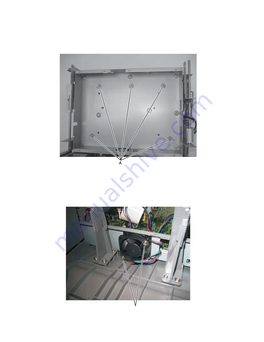
Controller board cage
1.
Remove the controller board. See Go to
“Controller board removal” on page 4-8
.
2.
Remove the five screws (A) which secure the controller board cage to the tub assembly.
3.
Tilt the front of the cage up and remove it from the MFP.
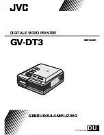
Controller board fan
1.
Remove the operator panel display. See Go to
“Operator panel display removal” on page 4-63
.
2.
Disconnect the controller board fan cable from J99 on the controller board.
3.
Remove the two screws (A) which secure the controller board fan to the controller board cage.
A
Summary of Contents for 3333DN
Page 1: ... 02 Nov 2009 ...
Page 2: ... ...
Page 10: ...x Service Manual ...
Page 15: ...Notices and safety information xv ...
Page 16: ...xvi Service Manual ...
Page 28: ...1 8 Service Manual ...
Page 31: ...General information 1 11 Reduce Enlarge 25 to 400 Copy only ...
Page 160: ...3 56 Service Manual ...
Page 172: ...4 12 2 Remove the three screws B securing the top of the controller shield B ...
Page 182: ...4 22 6 Remove the screw D from the gear E 7 Remove the plastic bushing F ...
Page 192: ...4 32 2 Carefully pull the scanner front cover away from the tub assembly ...
Page 205: ...Repair information 4 45 5 Remove the three screws B from the left door mount B ...
Page 208: ...4 48 8 Use a screwdriver to pop the inner shaft lock B loose 9 Remove the inner shaft lock C ...
Page 211: ...Repair information 4 51 5 Remove the e clip B 6 Remove the media feed clutch with cable C ...
Page 217: ...Repair information 4 57 7 Open the front access door and remove the lower paper guide B ...
Page 219: ...Repair information 4 59 5 Remove the three screws B from the left side of the printer B ...
Page 250: ...4 90 12 Disconnect LSU HSYNC extension cable at the connector in the middle of the cable ...
Page 251: ...Repair information 4 91 13 Remove the three screws A from the left rear frame assembly A A A ...
Page 252: ...4 92 14 Remove the three screws B from the right rear frame assembly B B B ...
Page 282: ...6 2 Service Manual ...
Page 284: ...7 2 Service Manual Assembly 1 Covers 3 11 7 13 5 16 9 15 2 10 6 17 4 12 8 14 1 17 18 ...
Page 286: ...7 4 Service Manual Assembly 2 Imaging 3 11 7 13 5 16 9 15 2 10 6 4 12 8 14 1 ...
Page 288: ...7 6 Service Manual Assembly 3 Tray assemblies 3 2 1 5 4 ...
Page 296: ...7 14 Service Manual ...
Page 304: ...I 8 Service Manual ...


