Danfoss AK2-SC 255 Reference Manual Download Page 120

RS.8D.M1.22

AK2-SC 255 Reference Manual

119

“rolling demand” using a “sliding window.”

About soft starts

The effect of a soft start is to slowly add load to the generator after it starts.  If, for
instance, soft start begin level is set to 6, when the generator starts only refrigeration
loads and loads assigned level 7 through 11 will be on.  After one minute, if the load is
below the “start shedding at” percentage of maximum emergency load, level 6 will be
turned on.  After another minute, the same decision will be made for level 5, and so on
down to level one.  If at any time the load reaches the “start shedding at” percentage,
load shedding will begin again until the system reaches the “start restoring at” per-
centage.

Configuring
 demand limiting

One utility meter per AKC 55 will allow configuration for demand limiting.  Configur-
ing demand limiting strategy is a two-step process.  First you select the meter to be
used for demand limiting and enter the parameters; then select the loads to be shed
for limiting demand and give each a priority.

In order to use demand limiting, you must have a Danfoss-approved utility meter with
Echelon interface and, if you are going to establish both normal and emergency load
limits, you must wire and configure an on/off input for the automatic transfer switch.
In addition, if the site has a coupling switch, you must wire and configure an on/off
input for the coupling switch.

You may wish to read the section “How demand limiting works”  that follows the
section “Lighting demand limiting,” before you start configuration. Now return to the
Energy menu (one good way is to return to the Main Menu (menu key), select
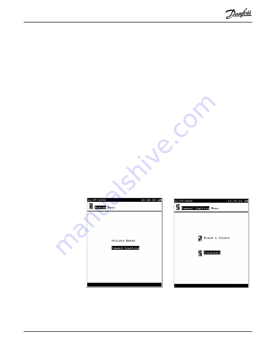
Energy, then select Demand Limiting. From the Demand Limiting menu, select
Configure.  These two screens look like this:

HVAC
demand  limiting

When you put the cursor on Configure, the second page of the Demand Limiting
Menu appears as at left below, offering two choices:  Select Units (for HVAC) and
Select Zones (for lighting).  Choose Select Units and the screen at right (below)

Summary of Contents for AK2-SC 255

Page 1: ...REFRIGERATION AND AIR CONDITIONING AK2 SC 255 Reference Manual Users Manual...

Page 2: ...RS 8D M1 22 AK2 SC 255 Reference Manual 1 AK2 SC 255 Rack Controller System Reference Manual...

Page 3: ...2 AK2 SC 255 Reference Manual RS 8D M1 22...

Page 4: ...rlier controllers If you can you should check the Danfoss web site at www acr danfoss com and select the menu item for product literature The AK2 SC 255 literature will be in the Supermarket electroni...

Page 5: ...d safety information 22 23 Neutral Zone control 23 Compressor capacity staging patterns 24 25 Configuring Evaporators 25 31 Case lights button 27 ConfiguringAK2 SC 255 refrigeration circuits 28 Config...

Page 6: ...nfiguration 75 76 RTU alarms configuration 76 RTU board points configuration 76 AHU Configuration 76 80 AHU fan configuration 76 78 AHR outside air coil configuration 79 80 RTC Configuration 80 93 RTC...

Page 7: ...setup 110 113 Board points configuration lighting 113 Powerlink configuration 113 Cutler Hammer configuration 113 Powerlink and Cutler Hammer board point configuration 113 Locate procedure 114 1 5 Ene...

Page 8: ...iscellaneous conversiosn 142 143 Miscellaneous calculations 143 144 Point creation 144 145 Custom strategy example 145 153 Creating the miscellaneous points Sensor inputs 145 146 Writing the custom st...

Page 9: ...rvice screen 175 2 5 Using the Communications Screens 176 187 Host Network screen 176 I O Network Status screen 176 177 List Points 177 179 List Nodes 179 180 IP Network Ethernet 180 181 Alarm routing...

Page 10: ...RS 8D M1 22 AK2 SC 255 Reference Manual 9 Overrides using the Manager s Override box 199 200 Keyswitch Override for refrigeration high temperature alarms 200 2 9 Using the Audit Trail 200 202...

Page 11: ...10 AK2 SC 255 Reference Manual RS 8D M1 22...

Page 12: ...may be limited to such items as are necessary to check out the mechanical equipment or provide basic service The configuration can be changed or added to at any time later Battery The unit s backup ba...

Page 13: ...apter 5 Using the System Using menus To select from any SC 255 menu first use the arrow keys to move the cursor to the item you want then press the ENTER key You can use the EXIT key to retrace your s...

Page 14: ...may have been partially configured by the rack manufacturer In that case when you select Refrigeration from the Main Menu the SC 255 will display the Refrigeration Menu left It lists the rack or racks...

Page 15: ...entries that you need to spell out The Rack label field contains a label one character in length The Oil type field is also a label field but it is 9 characters long allowing you to spell out a word...

Page 16: ...the list box s cursor on the selection you want press ENTER to save your selection Some list boxes contain only two choices for example Yes and No in the Monitor phase loss field Some may contain many...

Page 17: ...only one way to add a rack From the Main Menu select Configuration then Refrigeration and the Rack Configuration screen appears At the bottom left of the screen are the words Add Rack Move the cursor...

Page 18: ...evealed The fields and their contents are as follows Suction I D 2 label fields the first is a list box A to Z the second is 9 characters not constrained This is the identifica tion you wish to assign...

Page 19: ...t 50 0 to 100 0 The temperature that the adaptive control algorithm will seek to maintain in the fixture Does not appear when dynamic adaptive control is selected Range 0 0 to 100 0 The dead band arou...

Page 20: ...itor desuperheat temp List box Yes No Close EEV valves during rack shutdown List box Yes No If suct above target by 0 to 999 9 Number of psig above target when AKV valves will be closed during rack sh...

Page 21: ...down Control desuperheater List box Yes No Whether or not de superheater control is implemented on this rack Controlling sensor List box Desuper In AA Control is based on a sensor moni toring the liqu...

Page 22: ...by the respective unloader Inverter control List box Type of variable speed control None No inverter control VO An inverter is controlled by an analog output variable output VLT A Danfoss VLT adjusta...

Page 23: ...l pressure On Off Adigital input on off input is used to monitor an oil pressure switch Copeland A Copeland oil monitor is used Lockout comp on oil fail List box Yes No Whether or not compressors will...

Page 24: ...rises above the setpoint the time for lockout will restart from zero Disch pressure safety List box Yes No Whether or not comrpessors are to be cut out on high discharge pressure Cutout 0 0 to 500 0 T...

Page 25: ...isplay that results will show a row compressor icons for each stage A compressor s unloaders are represented by the small rectangles to the right of the compressor icon In the sample screen compressor...

Page 26: ...n In this manual we will discuss the configuration of SC 255 circuits and AKC 16x circuits For the other types of evapo rators please see the manuals on the individual controllers In the future when a...

Page 27: ...ons Maximum concurrent electric defrosts Appears only if Auto defrost schedules is enabled 0 to 20 The number of electric defrosts that can be underway concurrently Include dripdown time Appears only...

Page 28: ...lights to be switched on or off On Auto Choices are ON or automatic operation Off Auto Choices are OFF or automatic operation On Auto Off All three choices are available with a three position switch b...

Page 29: ...etpoint 0 0 to 120 0 each stage has a separate setpoint The temperature at which the subcooling stage will become active Temperature is measured by a sensor at the liquid outlet of the subcooler Cutou...

Page 30: ...st box Yes No Whether or not a box door switch will be monitored appears for boxes only Shutdown when door open List box Yes No Whether or not to shut down refrigeration when the box door is open No c...

Page 31: ...e requirements set on this page must be satisfied for defrost to terminate List box Various termination strategies are listed Defrost sensor There is a dedicated defrost tem perature sensor that will...

Page 32: ...above 0 0 to 100 0 The dewpoint above which anti sweat heaters will be on constantly Cycle above dewpoint 0 0 to 100 0 The dewpoint above which anti sweat heaters will be cycled Cycling will occur unl...

Page 33: ...mination has not occurred on a setting configured in the previous screen Often called fail safe defrost time Defrost start time time of day one field for each of the number of defrosts configured in t...

Page 34: ...ration can be shut down for cleaning or other service Shutdown schedules Paging down we reach the shutdown page s There are two schedules per page Each schedule has a field for time on time off days o...

Page 35: ...on defined in the alarm routing screen at the interval set in the alarm routing screen from 10 to 99 minutes the default is every 10 minutes Delete The alarm settings will no longer appear on the scre...

Page 36: ...n the configuration screen for air cooled condensers when Sat Cond Temp is selected as the Control sensor The change to saturated condensing temperature control strategy causes several of the followin...

Page 37: ...s with a digital input created for each pair Control sensor List box Pressure A pressure sensor will be used to control the condenser fans An analog input sensor input will be created for the sensor D...

Page 38: ...ed up When a stage is at maximum speed and additional fan capacity is needed the stage will be dropped to minimum speed and the next stage brought on at minimum speed then ramped up as required Neutra...

Page 39: ...00 0 for temperature sensors The value that the control algorithm will seek to maintain with the selected strategy The next page has settings for high pressure bypass and for inverter control if used...

Page 40: ...nufacturer s specifications RPM at max speed 1 to 6000 The RPM at the maximum percentage specified in the previous setting Inverter max resets 10 to 10 The maximum number of inverter resets after whic...

Page 41: ...will be split Split deadband 0 0 to 25 Only with single split valves The deadband above the previous setpoint in which unsplitting cannot occur Drop fans List box Even Odd Only with single split valve...

Page 42: ...e condenser control algorithm reacts with normal sensitivity Plus Zone 10 to 900 The PI algorithm sensitivity when current control sensor value is above the normal reaction zone Minus Zone 10 to 900 1...

Page 43: ...ce from condenser to the rack Open SPR if discharge 0 0 to 200 0 The pressure differential above target at which the system pressure regulator will open Bleed valve List box Yes No Whether or not ther...

Page 44: ...pears if control is by pressure Whether the drop leg temperature will be monitored A Yes answer here will create an analog input sensor input for the drop leg temperature sensor Control method List bo...

Page 45: ...the second page following and change Fan inverter control to the appropriate variable speed control either VO or VLT to restore the variable speed choices here Rate of change A control strategy that s...

Page 46: ...fill at which the fill valve will open and top off will begin Fill valve List box Yes No Whether or not the sump fill valve is controlled Monitor inlet temp List box Yes No Whether or not the inlet te...

Page 47: ...echnician is required to clear the bypass by using the appropriate button in the status screen Freeze Protection List box Yes No Whether or not freeze protection control is implemented Freeze prot tem...

Page 48: ...surge control will be implemented Cutin 0 0 to 100 0 The temperature at which the surge valve opens Cutout 0 00 to 100 0 The temperature at which the surge valve closes Liquid level sensor type List...

Page 49: ...age will be turned off Stage 2 type The same choices as for Stage 1 type and setpoints are offered Flush Cycle List box Yes No Whether or not there is to be a flush cycle Flush Cycle Start Time Time o...

Page 50: ...of the rack are presented The first page of suction alarms is shown at right above One of the list boxes has been opened to reveal its options For each alarm the first line contains an alarm type the...

Page 51: ...the field then press the key then use the arrow keys to scroll through the settings then press ENTER What You Can Change in a Standard Alarm Standard alarms are the alarms that are automatically crea...

Page 52: ...The default names for the outputs automatically added during configura tion of refrigeration are shown and will suffice in many applications They can be edited character by charac ter put the cursor o...

Page 53: ...n the same line as PG DN for more is the SORT field By default sort mode is on and entries will be sorted by Bd Pt address if sort mode is turned off points from then on will be listed in order of cre...

Page 54: ...t point enter the board and point address of the sending point Type List box AKS 32 100 Danfoss pressure sensor 0 to 100 psig AKS 32 200 Danfoss pressure sensor 0 to 200 psig AKS 32 500 Danfoss pressu...

Page 55: ...on and entries will be sorted by Bd Pt address if sort mode is turned off points will be listed from then on in the order in which they were created The sorting occurs when you press EXIT and will be...

Page 56: ...Voltage The point will be read as ON if it senses no voltage It will read OFF when it senses voltage Latching The point will be read as ON when it first senses a momentary voltage It will continue to...

Page 57: ...t it press ENTER Bd Pt Enter the Bd Pt address to which the load is wired Range List box two variable output ranges are available depending on the drive requirements 0 10 Volts 0 5 Volts SORT At the b...

Page 58: ...Smart Case Controllers The fields and contents are Name Label field any 15 characters The name of the evaporator being controlled by the AKC 16x AKC 16x refers to AKC 161 AKC 164 or AKC 165 controller...

Page 59: ...ations 2 From the Communications Menu select I O Network 3 From the I O Network Menu select Re scan Re scanning the network can take several minutes After the re secan return via the Main Menu to the...

Page 60: ...e set using the buttons on the EKC The installer should provide a list with the address for each fixture If such information is not available obtain the address at the fixture from the EKC by using th...

Page 61: ...is done from the Degree Master Controls Board Points screen From any Configuration Board Points Other Controllers screen select the Degree Master Icon and press ENTER This screen appears Our example...

Page 62: ...from the display After starting the locate procedure from the SC 255 keypad it is possible to activate the service pin from the Degree Master s display Press and hold both buttons for 3 seconds When t...

Page 63: ...ield press to change to edit mode then use the left and right arrow keys to move from space to space and the up and down arrow keys to select the character for that space When the name appears as you...

Page 64: ...n Menu Evaporator Menu shown above on the right are as follows No of HVAC Units 0 to 45 The number of controlled HVAC units of all types in the store No of phase loss monitors 0 to 45 The number of ph...

Page 65: ...5 The unit is controlled by a Danfoss or ECI ClimaTECH 65 controller CT 1024 The unit is controlled by a Danfoss or ECI ClimaTECH 1024 controller Carrier The HVAC unit is a Carrier Centurion or Carrie...

Page 66: ...will run on demand during closed hours On demand means that the fan will run whenever conditions calling for heating heat reclaim cooling dehumidification or venting are met Post delay 0 to 60 The nu...

Page 67: ...l be based on the lowest value of all of the supply air temperature sensors Max Temp Display will be based on the highest value of all of the supply air temperature sensors Average Display will be bas...

Page 68: ...ist Control will be based on the single selected temperature sensor Num of cooling stages 0 to 6 The number of cooling stages in this HVAC unit Target temp for stage 0 0 to 99 9 A separate field for e...

Page 69: ...he suction pressure for the cooling compressors in this rooftop should be used No cooling above 0 0 to 100 0 The pressure value of the sensor selected on the previous line at and above which cooling w...

Page 70: ...ing page s reached by using the PG DN key RTU Heating configuration Heating configuration for rooftop units begins with selection of Heating from the rooftop configuration menu Number of zone sensors...

Page 71: ...ere is to be a night setback for heat Night setback offset 0 0 to 50 0 The amount by which the heating setpoint set on previous page is to be lowered during times when night setback is scheduled Overr...

Page 72: ...turned off There is one field for each stage Lockout aux ht in setbk List box Yes No Whether or not auxiliary heat is to be locked out during hours when setback is effective Ambient heat lockout List...

Page 73: ...Auxiliary heat will be locked out above this temperature plus range next line Heat will be allowed on again when ambient temperature has fallen to lockout minus range Range 0 0 to 999 9 The range sele...

Page 74: ...t target which will be compared with a dewpoint calculated from inside zone temperatuare and humidity Both zone temperature and humidity sensors must be installed Inside Dew Dehumidification will be c...

Page 75: ...bove Target differential 0 1 to 15 0 The differential forms a deadband above and below the target in which no control actions are taken Dehumidification will be turned on at target plus differential a...

Page 76: ...umber of night setback schedules desired on the following schedule page s RTU Air Damper configuration For air damper configuration select Air Damper from the Configure RTU menu Air Damper List box Ye...

Page 77: ...VAC fan down for each fan speed HVAC phase loss for this unit s phase loss detector HVAC smoke for this unit s smoke detector HVAC fire for this unit s fire detector RTU Board Points configuration See...

Page 78: ...t box Continuous The fan will run continuously during hours when the store is not open Store open hours are defined in the Store Info screens On demand The fan will run on demand during hours when the...

Page 79: ...pm at max speed 1 to 9999 The rated maximum speed of the fan motor from the data plate Second page AHU Fan Configuration Reaction Time 1 to 20 This setting together with the next regulate the sensitiv...

Page 80: ...n Temp Control will be based on the lowest value of all of the supply air temperature sensors Max Temp Control will be based on the highest value of all of the supply air temperature sensors Average C...

Page 81: ...d Target temp for stage 0 0 to 100 0 One target per cooling stage excluding outside air coil stages The target temperature that you want the first stage to maintain at the zone sensor Range 0 0 to 9 9...

Page 82: ...demand The fan will run on demand during hours when the store is not open whenever heating cooling dehumidification or venting is called for Post delay 0 to 60 The number of minutes the fan will run a...

Page 83: ...by an decrease in load Variable Output range List box 0 5 Volts Sets the RTC board s analog output for a variable speed drive requiring 0 5 volts 0 10 Volts Sets the RTC board s analog output for a va...

Page 84: ...et temperature for the highest of a number of zone temperature sensors Zone 1 etc each supply zone temperature sensor will be available as a choice in the list Control will be based on the single sele...

Page 85: ...there will be no offset of target temperature Full 99 9 to 99 9 The relative humidity above which the maximum offset of target temperature by humidity will be applied Ambient temp lockout List box Yes...

Page 86: ...f the target is 72 and the range is 2 the stage will come on at 70 and will not be turned off until the temperature reaches 72 The pre delay and post delay must also be satisfied Target temp for stage...

Page 87: ...are two pages of dehumidification configuration settings Dehumidification type List box None Cooling The type of dehumidification used Aux heat during dehumid List box Yes No Whether or not auxiliary...

Page 88: ...s that must elapse after target minus range is reached before the stage will be turned off There is one field for each stage Cooling low limit 0 0 to 100 0 The temperature at and below which dehumidif...

Page 89: ...ity control will be based on the highest of two humidity sensors Zone 1 etc each zone humidty sensor will be available as a choice in the list Enthalpy or humidity control will be based on the single...

Page 90: ...Danfoss trained techni cian RTC schedules The RTC schedules screen s allow entry of schedules for operation of the rooftop RTC alarm configuration Alarms can be for any of the following in accordance...

Page 91: ...t The names are fixed since the hardware points on the RTC board are dedicated and can control only a single type of device as follows Point 1 Fan Point 2 Economizer Point 3 Cool 1 Point 4 Cool 2 Poin...

Page 92: ...here the address of the point that is to be received Configuring RTC I O on off inputs Here is the screen for on off digital inputs reached with the third icon from left Note that the screen is divide...

Page 93: ...names always appear as in the illustration above whether the input is used or not Bcast List field one for each point No The input is not configured or its state is not to be used by the controller R...

Page 94: ...nd can serve only for the listed outputs The names always appear as in the illustration above whether the input is used or not Range List field one for each point 0 10 Volt The output will supply 0 10...

Page 95: ...have some unique configuration requirements For these units select SC4 as the type on the Configure HVAC menu At left below is the SC4 menu At right is the screen for fan configuration Motor delay ti...

Page 96: ...e of all the zone temperature sensors Zone Temp 4 1 etc each zone temperature sensor will be available as a choice in the list Control will be based on the single selected sensor Num of cooling stages...

Page 97: ...turned on before the next stage can be turned on SC4 heating configuration No of zone sensors 0 to 5 The number of zone temperature sensors Controlling sensor List box Min Temp Control will be based o...

Page 98: ...ge for the lockout Heating will be locked out at lockout plus range and when locked out will be allowed on at lockout minus range Minimum run time 0 to 20 The number of minutes that a stage must run b...

Page 99: ...e is to be a lockout based on low ambient temperature No dehum below 0 0 to 100 0 The ambient temperature below which dehumidification will be locked out Range 0 0 to 9 9 The range for the lockout Deh...

Page 100: ...fans List box None Six Eight The number of HVAC condenser fans controlled in this unit Minimum run time 0 to 60 The number of minutes that a stage must run before being turned off Liquid Temp Setpoin...

Page 101: ...control capacity The ClimaTECH configuration menu appears below There are two fan configuration screens depending on whether the fan is fixed speed or variable speed Fan type List box Fixed Speed Vari...

Page 102: ...rated fan speed allowed Heat Dehumid fan speed 0 0 to 100 0 The percentage of rated fan speed during dehumidification or heating Shutdown on fire alarm List box Yes No Functional only if the fire alar...

Page 103: ...pied setpoint 0 0 to 150 0 The heat reclaim setpoint during store closed hours as configured in the Store Info screen Lockout above ambient 0 0 to 150 0 The outside ambient temperature above which hea...

Page 104: ...uxiliary heat is on Valve delay 0 to 99 The number of seconds after the enabling relay turns on before the analog valve can open ClimaTECH dehumidification configuration Num of stages 0 to 6 The numbe...

Page 105: ...onomizer configuration Economizer List box Yes No Whether or not there is an econo mizer function in the HVAC unit Outside ambient target 40 0 to 150 0 The target The number of stages of auxiliary hea...

Page 106: ...ure etc or on off state can be set for each alarm ClimaTECH schedule configuration Because the ClimaTECH can function as a stand alone it contains its own schedules They are set for each day and holid...

Page 107: ...screens to allocate these An input or output number from 1 up to the limit of the controller is entered under the stage number in the case of relay outputs ClimaTECH sensor inputs Zone temp group 0 to...

Page 108: ...TP1 OI The input is an on off input 0 10 Volts This type can be used for any sensor whose output is linear from 0 10 Volts Function List box Control Monitor For zone sensors only whether the point is...

Page 109: ...ClimaTECH controller Go to the controller and depress the service pin After completing the Locate procedure place the cursor on the Init field and press ENTER Uploading to the AK2 SC 255 If the Clima...

Page 110: ...ch Num of schedules 0 to 8 The number of operating schedules entered on the following page s Config List box No Rec No The sensor is not used Rec A sensor value is received from the system s I O netwo...

Page 111: ...r of Cutler Hammer Pow R Line C Switchboard lighting panels to be configured Zones share photocells List box Yes No Whether or not multiple photocells are to be shared Number of photocells 0 to 8 The...

Page 112: ...The number of schedules for this point Photocell List box Inside The point s photocell s are indoors Outside A single photocell is located outdoors None This point has no photocell Control sensor List...

Page 113: ...level Photocell range 0 to100 The number of percent from night to day Trip Level 0 to100 The level at which the photocell condition will be true and act to turn the lights on If multiple relays are co...

Page 114: ...a moni tored burglar alarm is sensed Pre delay 0 to 600 When this zone s lights are off and a burglar override is called for the number of minutes delay before the zone is turned on Fire override Lis...

Page 115: ...erlink panels require that you put the cursor on the Locate field and press enter A popup box will appear on the screen instructing you to press the service pin on the breaker panel You will have a fe...

Page 116: ...ight below Continuing select Configure from the Utility Meter Menu and press ENTER Now the Utility Meter Configuration menu appears as shown below Enter the number of meters to be configured and a lis...

Page 117: ...s entered here are the same as the values entered at the meter Number of CT sets EMON only 0 to 5 The number of meters sets of current transformers connected to this meter Wattnode assumes a single se...

Page 118: ...meter The page looks like this The fields in the screen are these Maximum emergency load Demand limiting only 0 to 99999 Enter the upper demand limit that you do not wish to exceed when the emergency...

Page 119: ...ll be turned on when the emergency generator starts A level will be added each minute unless the specified emergency load for shedding to start is reached Coupling begin level Emergency generator cont...

Page 120: ...o be used for demand limiting and enter the parameters then select the loads to be shed for limiting demand and give each a priority In order to use demand limiting you must have a Danfoss approved ut...

Page 121: ...by the number of steps allowed Levels above the number of steps configured will not be shed unless the meter configuration is changed Since there are only up to ten steps loads assigned level 11 will...

Page 122: ...are skel eton in nature This means that the alarms are now allocated in the program but you should inspect the alarm actions trip levels and time limits for each alarm and adjust them accordingly to m...

Page 123: ...C and another submenu will appear listing all the different parts of the system for which we can configure alarms Note the last item on the menu at right above Bitzer This appears only because when th...

Page 124: ...nfiguration settings if any will remain in memory for future activation All alarms are in this state initially until you change them Adescription of each enabled alarm action follows Log Only The occu...

Page 125: ...ary to be authorized for refrigeration functions or the higher Supervisor level To suspend rack alarms select Refrigeration from the Main Menu then select the rack being serviced from the refrigeratio...

Page 126: ...vel for the alarm move the cursor to the next changeable field Because we are configuring a digital alarm that is constrained to a value of On the only remaining fields we can change are for the time...

Page 127: ...ult alarm pressure and time settings that appear as soon as the alarm action level is changed to something other than disabled In the screen at right above we have moved cursor first to the pressure s...

Page 128: ...nd low suction pressure alarms Start by considering the target pressure that is configured for the rack Know the range of pressures that the rack will operate in when loads product temperatures defros...

Page 129: ...to 9999 seconds minutes or hours High Pressure if a suction pressure sensor is configured An analog alarm set for a pressure from 999 9 to 999 9 psi or bar and a time limit of from 1 to 9999 seconds...

Page 130: ...econds minutes or hours High Temperature if a discharge temperature sensor is configured An analog alarm set for a temperature from 999 9 to 999 9 degrees with a time limit from 1 to 9999 seconds minu...

Page 131: ...nt sensor temperature appears along with the number of the I O board and point to which the case temperature sensor is wired At first you see two alarms both disabled In the screen at right above we h...

Page 132: ...and by having configured a miscellaneous point for the switch which is then wired to that point The logic written for the miscellaneous point will prevent alarms after the switch is operated for the t...

Page 133: ...a tion of defrost and the specified temperature is not reached before the time set for fan delay expires Drip pan clogged Occurs when a clogged drain is sensed due to standing water in the fixture dri...

Page 134: ...ve only the first page of alarms Depending on the number of fans there may be additional condenser fan failure alarms on a second page High Pressure discharge pressure sensor This same alarm appears o...

Page 135: ...nutes or hours Low liquid level if a liquid level sensor is configured An analog alarm that occurs when receiver liquid level has fallen below water temperature is below a set percentage but values fr...

Page 136: ...m the Main Menu select Configuration then Alarms then HVAC The alarm configuration menu is shown at left below When you select HVAC from the alarm configuration menu a list menu headed Configure HVAC...

Page 137: ...period of from 1 to 9999 seconds minutes or hours High humidity Occurs when zone humidity is above a set percentage the field takes values from 999 9 to 999 9 for a period of from 1 to 9999 seconds mi...

Page 138: ...er elapsed Occurs when the set number from 1 to 9999 seconds minutes or hours have elapsed Useful when set for the system air filter life as a reminder to change the filter Filter runtime Occurs when...

Page 139: ...controller has a digital input to detect failure of the HVAC system s inverter if the system is a variable speed unit This alarm occurs when the inverter has been called for for the specified alarm de...

Page 140: ...ight The first icon represents relay outputs the current screen The others from left to right are in reverse video unselected and represent analog inputs digital inputs analog outputs and casc control...

Page 141: ...cursor is by default on the Number of alarms field We can enter any number from 0 to 3 We want to configure only one alarm Entering 1 in the Number of alarms field produces the screen at left below Be...

Page 142: ...there are any miscellaneous points already configured First select Miscellaneous from the Main Menu Select Configuration and the Configure Miscellaneous Menu appears The calculated points feature of S...

Page 143: ...scellaneous calculations section which follows in a few pages Miscellaneous on off inputs You can configure up to 64 miscellaneous on off inputs per SC 255 To configure miscellaneous on off inputs sel...

Page 144: ...a full complement of argument types and operators Examples follow this section Right now let s investigate the screens one by one as far as we can in general If there are no calculations configured w...

Page 145: ...first displays showing all the types of points that can be created and for SI points units For the purpose of discussing the screen let s assume that we are creating an OI a digital input We select O...

Page 146: ...essor room temperature is 90 F or higher we also want it to run in case of a refrigerant leak of 500 ppm or more So let s list the types and values we will need OI calculated point to control the RO S...

Page 147: ...point for the miscellaneous RO we created Notice the Undo and Cancel button fields in the heading of the screen Undo will erase your last step if you make a mistake Cancel will undo all changes leavin...

Page 148: ...d for the sensor changes from error to 0 0 F Still in the data definitions area select the blank in the second line under Name and open the list box This time select Number F from the list be careful...

Page 149: ...t left below Toggle to edit mode and as you can see at right the opportu nity to insert a new line presents itself Now press ENTER and the new line appears On the new line create argument SI3 an SI pp...

Page 150: ...l mathematical operators appropriate to sensor inputs We will select as the operator for this statement Having done that move one field to the right and select Num2 as the argument to complete the sta...

Page 151: ...line There must be one true state ment called the else statement by logicians So the last line always states True with the result set to whatever state we want when none of the other conditions is tr...

Page 152: ...t Name Label any 15 characters Edit the field to read appropriately to the purpose Bcast List box No Send Rec Leave the Bcast field set to No We are not going to use the point elsewhere on the network...

Page 153: ...o things to add to configuration here Control Input List box all configured OIs Our new calculated OI is found at the bottom of the list Use the three dots at the top or bottom to move up or down the...

Page 154: ...ulated point Higher numbered points will remain in place The deleted point will be the next new point made available for configuration Style To understand the various styles of Calculated SI and OI po...

Page 155: ...undo or cancel and reverses that action Configuring Authorization Only users authorized at the Supervisor level have sufficient access to configure authorization Supervisors can select Authroization...

Page 156: ...Store Info from the Main Menu then Units Languages This is the screen that displays The fields are these Pressure List box PSI bar Temperature List box F C Date List box four date formats are offered...

Page 157: ...156 AK2 SC 255 Reference Manual RS 8D M1 22...

Page 158: ...if it isn t the screen you see on the controller by pressing the MENU key Here s the Main Menu Authorization Just Looking If you are just looking at information in the system you may not need to enter...

Page 159: ...Authorization from the Main Menu This is the screen that will appear Notice that the current level of access probably View only will be seen at the top of the screen The cursor will be in the Auth fie...

Page 160: ...h the Units Languages screen which looks like this The fields in the screen are these The selections are self explanatory Pressure List box psi bar Temperature List box F C Date List box a choice of 4...

Page 161: ...ration menu many be different In this menu there is some status information displayed the current suction pressure and for reference the target suction pressure Since there is more than one rack being...

Page 162: ...AA we ll see our first detailed status screen Notice that there is a row of icons across the bottom of the screen The cursor is on the third icon suction which is shown in reverse video From left to r...

Page 163: ...have left the menu to enter the main body of the screen you can return to the icon menu by pressing the MENU key When using a PC you can back up one screen by clicking in the screen title area Viewing...

Page 164: ...and use the icon menu to enter the Suction Schedules screen Press MENU to return to the icon menu at the bottom of the screen Move the cursor to the schedules icon which looks like a clock face with...

Page 165: ...of such a field and describe how to change it we will go back to the Main Menu and select Store Info then Holidays Changing names was covered in Chapter 5 7 but we ll repeat the information here The...

Page 166: ...maintenance Typical is the Suction Service menu reached by selecting the service icon from a Suction Status menu Auto Manual Relays The first two selections are similar Select Auto Manual Relays and a...

Page 167: ...the arrow keys to change the field and then press ENTER Reset In the center at the bottom of the screen is a Reset field If you place the cursor on this field and press ENTER all relay outputs will b...

Page 168: ...e value the sign will not change until you enter the first numeral from the keypad You can only offset a real sensor you cannot enter an offset for a reading being received from another controller And...

Page 169: ...t AKV valves Fixture temperature is below target range minimum The valve percentage will hold at zero closed The evaporator will remain in this status until fixture temperature rises to target when th...

Page 170: ...rns the dynamics of the evaporator and optimizes internal parameters for the modulated control function After fixture temperature reaches its target if that target is between 23 F and 50 F and after a...

Page 171: ...for a maximum of two minutes to establish minimum superheat When fan delay is finished and minimum superheat is reached status will change to Cut in After drip down KVQ valves operate normally until...

Page 172: ...hut down using the service screen either for case cleaning or other service The screen at left below is the second page of an evaporator status screen Evaporator Settings Smart Case Control If you sel...

Page 173: ...ation the defrost will be skipped Evaporator Schedules Smart Case Control The schedules screen for an evaporator shows the number of defrost scheduled per day the duration and the start time for each...

Page 174: ...r Maxi mum Time which is the maximum time a system can remain in defrost whether or not a selected termina tion temperature has been reached There are two fields which control the mode of the fixture...

Page 175: ...circuits with Smart Case Controllers Evaporator Status Screen The status screen for an SC 255 circuit is reached from the main menu by selecting Refrigeration then the Rack then Evaporators then the e...

Page 176: ...ttings Screen The settings screen reached by selecting the settings icon at the bottom of the screen shows and allows changes to settings for refrigeration and defrost Evaporator Schedules Screen The...

Page 177: ...menu will appear Host Network Screen The Host Network screen shows the address of the current 255 the number on the network and the status Online or Offline of each Our example below shows o0nly one...

Page 178: ...tton the screen at right above appears List Points Select List Points from the I O Network Status Screen and this is the screen that appears The fields and their contents are as follows Bd Pt The addr...

Page 179: ...left of the body of the screen above the icons on the same line as PG DN for more is the SORT field By default sort mode is On and entries will be sorted by Bd Pt address If sort mode is turned Off p...

Page 180: ...trollers List Nodes The List nodes screen reached from the I O Network Status menu looks like this The list nodes screen shows the type address and status of every node on the I O network In the sampl...

Page 181: ...d is an IP address and is the address of the ethernet node to which alarms are to be sent The IP address is assigned by your network administra tor The address is composed of four one two or three dig...

Page 182: ...e numbers one or both of the IP network addresses to one of up to three OAB s to a local printer or to any combination of destinations The destinations are indicated by the column heads and subheads a...

Page 183: ...and each Alarm Box are correct For alarm boxes the SC 255 where the alarm box is installed must have a relay output board and point assigned for the box Printer Settings Screen To receive alarms a se...

Page 184: ...ese schedules is true Up to three standard schedules can be set up In order to activate the schedule it is necessary to toggle the field reading Not Used to Standard Then the schedule settings will ap...

Page 185: ...the proper commands If the modem was supplied by Danfoss instructions will accompany it or you may call Danfoss Technical Support for assistance Baud Enter the transmission speed in baud or bits per...

Page 186: ...the line being used This is the number you would dial on this line using a telephone instrument to reach the destination Up to twenty characters can be entered The following special characters have t...

Page 187: ...type of receiving device either Printer or AKA 65 Init An extra initialization string which may be needed for some modes of communication Default is AT The entry is user editable Date The date format...

Page 188: ...ve Remember to toggle edit mode for each line by pressing the key and press ENTER at the end of each line 2 6 Using the History Screens for History Retrieval To view history select History from the Ma...

Page 189: ...eld to Yes and press ENTER Note that this can only be done if there are not five points already selected and shown in the upper portion of the screen If all five positions in the upper portion of the...

Page 190: ...emain unaf fected Also see the paragraph on Auto View following the next illustration Clear Clears the column labeled view in all the Configure History Display screens for all the points represented b...

Page 191: ...croll field regulates how much of the screen will be scrolled when you press one of the small arrow buttons in center bottom of the screen The selections possible are Full for full screen scroll Half...

Page 192: ...x settings on the bottom line of the display Min can be any multiple of 10 from 90 to 90 Max can be any multiple of 10 from 80 to 500 Time The times given at left and right below the graph are the beg...

Page 193: ...ay of statistics for the four points selected The statistics given depend on the type of point whether on off relay outputs on off inputs or variable sensor inputs variable outputs calculated values H...

Page 194: ...but whose condition is no longer out of bounds whether or not the alarm has been acknowledged Any cleared alarms among the most recent 100 alarms will be displayed in the Cleared Alarms screen Alarm S...

Page 195: ...e alarm Two fields on the right of the screen deserve special explanation Now The present status of the alarm condition For system alarms mo dem I O comm Test Alarms etc the field will read Trip For a...

Page 196: ...ion that appears in the top blue border of every SC 255 screen will be turned off 4 The Ack field in the Active Alarms screen or the Cleared Alarms screen will be changed to Yes 5 In the detailed alar...

Page 197: ...100 active and cleared alarms for all the SC 255 s in the network The format of the screen is the same as the format of the Active Alarms screen and the Cleared Alarms screen which are discussed above...

Page 198: ...on in this SC 255 only Send Test Alarm Sends a single test alarm The Generate system test alarm function see below must be enabled Generate system test alarm Provides a means of generating a test alar...

Page 199: ...et switches on RO8S boards the Manager s Override box and the keyswitch override Overrides Using Service Screens A typical service screen is the one for relay output boards There is a similar screen f...

Page 200: ...and common terminals Output LED s Each output has a pair of LED s one red and one green The red LED lights whenever its relay output is overridden The green LED lights whenever the relay coil is energ...

Page 201: ...he Audit Trail The SC 255 audit trail is a log that shows each system access together with any changes to configuration or settings that were made during the access The audit trail log shows every sys...

Page 202: ...and only the supervisor level should see authorization codes If a supervisor wants to see the codes the authorization configuration screen to which no one else has access will show them all At the sa...

Page 203: ...one entry back ward in time an operator that moves the screen one page back ward in time 00001 shows the oldest entry in the audit trail database When the database is filled to capacity the next entr...

Page 204: ...RS 8D M1 22 AK2 SC 255 Reference Manual 203...

Page 205: ...204 AK2 SC 255 Reference Manual RS 8D M1 22...

Page 206: ...Danfoss Refrigeration Air Conditioning Division 7941 Corporate Drive Baltimore MD 21236 Tel 410 931 8250 Fax 410 931 8256 Direct Order Fax 410 931 0677 www acr danfoss com RS 8D M1 22 Danfoss 2005...

Reviews: