


Chapter 6 - Hydraulic Brakes
178
Brake drag / pulling (if at front caliper)
•
Caliper frozen on slide pins
: After a long
period of dis-use or extremely gentle use, the
calipers may have become stuck on the slide
pins by corrosion or debris.
When pressure is applied to the piston in the cal-
iper, the inside pad contacts the rotor, and the
body of the caliper normally slides in the oppo-
site direction, pulling the second brake pad
against the outside of the brake rotor.
If the caliper is frozen on the pins, the inboard
brake pad will drag on the inner surface of the
brake rotor. Accelerated wear of the inboard
pads and rotor surface of any caliper are a tell-
tale sign of this condition.
•
Caliper piston stuck
in bore. This is an
unusual problem, but it can happen on any disc-
brake design. Accelerated wear of both pads on
any single rotor is the primary indicator. If the
vehicle is operated for any length of time, the
rotor surfaces will be blued from over-heating.
•
Damaged brake line
. After many years of use, it
is possible for the interior lining of some flexible
hoses to disintegrate or “implode”. This will
cause sluggish action in both directions. The
caliper(s) on the effected wheel(s) will apply
slowly and release slowly. Typical customer
complaint if a front brake line is effected will be
that the steering wheel pulls in one direction
while the operator applies the brakes, but pulls
in the opposite direction when they accelerate
away from a dead stop.
•
Master cylinder / brake pedal
not returning
.
This would most likely result in brake drag accel-
erated wear and blued rotors at all four wheels.
Check for bound pedal linkage. Do not over-
look the possibility that the operator may be rest-
ing their left foot on the pedal.
AT-WHEEL COMPONENTS
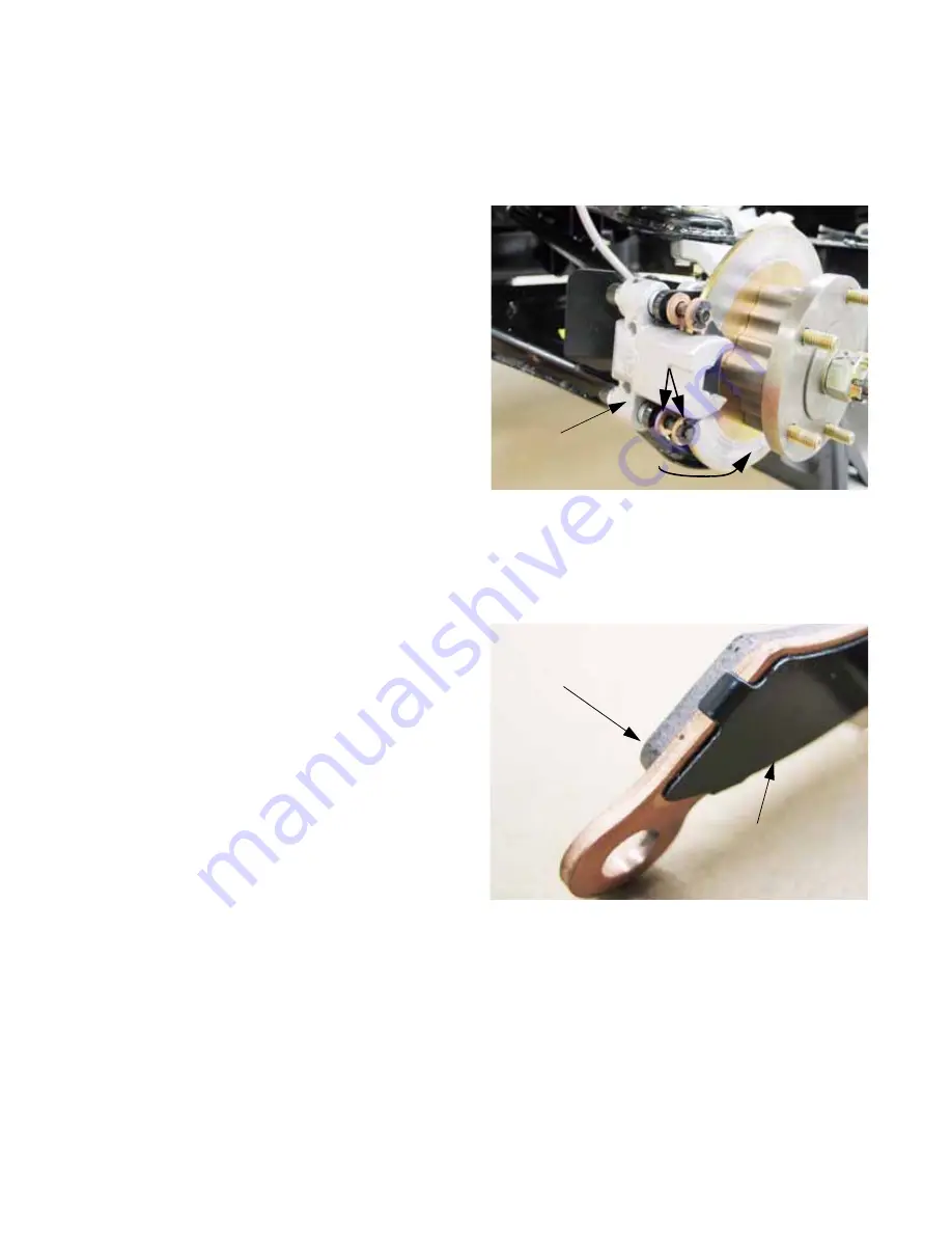
The
brake calipers
(single-piston, floating) are identi-
cal front to rear, and the pad replacement method is
identical as well. See Figure 6.11.
Each
brake pad
has an anti-squeal plate bonded to the
back side of the pad. Original thickness of the friction
material is roughly .156” (4mm).
See Figure 6.12.
•
The anti-squeal plate is attached by adhesive
and clips.
•
The clips extend roughly .020” (.50mm) over the
friction surface side of the pad, and act as an
audible wear sensor when the friction material is
worn to less than .020”
•
Replace the pads when the friction material
thickness is less than .040” (1mm).
Figure 6.11
Front brake caliper
Brake pads
Brake rotor
Figure 6.12
Brake pad
Anti-squeal plate
Summary of Contents for Volunteer 4x4 Utility Vehicle
Page 2: ......
Page 4: ......
Page 12: ...Chapter 1 Introduction 8 ...
Page 66: ...Chapter 2 Drive System CVT and Transfer Case 62 ...
Page 78: ...Kohler Enclosed CVT Addendum 74 ...
Page 92: ...Caterpillar Enclosed CVT Addendum 88 ...
Page 126: ...Chapter 3 Drive System Drive Shafts and Differentials 122 ...
Page 278: ...Chapter 8 Caterpillar Engine and Related Systems 274 ...
Page 319: ...Chapter 9 Electrical 315 Electrical Schematic Engine Harness w Kohler engine ...
Page 321: ...Chapter 9 Electrical 317 Electrical Schematic Engine Harness w Caterpillar engine 725 04341 ...
Page 322: ...Chapter 9 Electrical 318 ...
Page 327: ...5 ...
Page 328: ...6 ...