


Chapter 3 - Drive System: Drive Shafts and Differentials
120
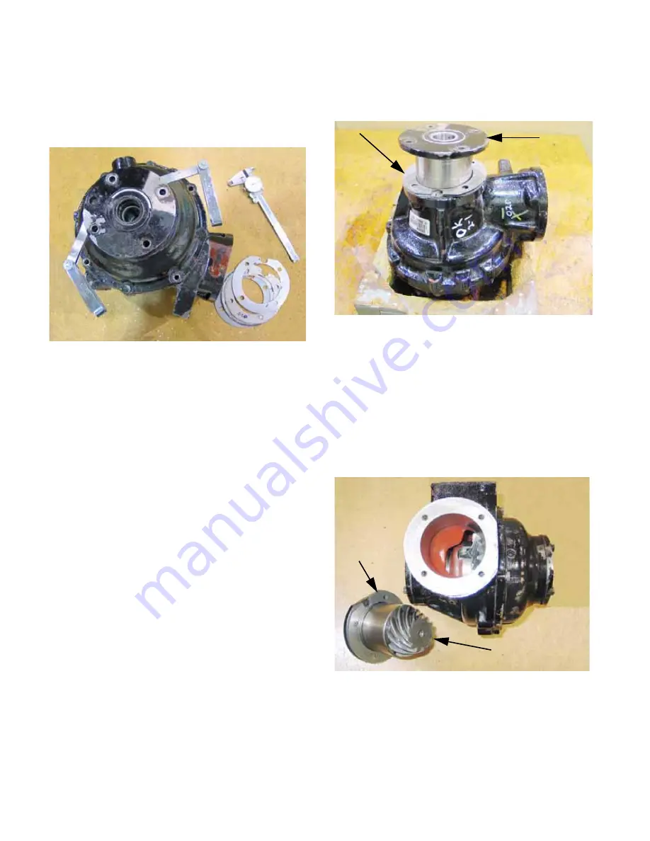
6a. The first step is to set the pre-load on the
carrier bearings. Pre-load is set with the
total number of shims separating the car-
rier bearing cartridges from the differential
housing. See Figure 3.87.
•
Assemble the differential, except for the pinion
cartridge, with no shims in place.
•
Carefully tighten the right side carrier bearing
cartridge: It should be tight enough to seat the
tapered roller bearings, but not so tight as to dis-
tort the cartridge. Pressure must be even on all
four screws, leaving an even gap between the
mating surfaces of the cartridge and the differen-
tial housing all around the contact point.
•
Measure the gap.
6b. Install the number of 1.0mm shims that will
bring the gap as close as possible to zero,
then tighten the carrier bearing cartridges
and differential housing halves together.
•
Better slightly loose than tight.
•
Confirm adjustment by checking end-play of the
differential. A dowel rod having an outside diam-
eter from 3/4” to 7/8” (19-22mm) can be used to
press against the long cross-shaft in the differen-
tial. A shorter dowel of the same size can be
inserted from the opposite side, providing a flat
surface for a dial-indictor to register against.
6c. Once the number of shims is correct, the
distribution from left-to right must be
determined. See Figure 3.88.
•
In the absence of other information, the best
place to start is with the shims evenly distributed
between the two sides.
6d. The final step in the shimming process is
to set rotational back-lash and gear mesh.
The two steps happen together: the shims
on the pinion cartridge and the carrier
bearing cartridges are all used to achieve
the correct end-result. See Figure 3.89.
•
Adding shims to the pinion cartridge increases
back-lash, moves the contact patch toward the
nose of the pinion gear and outward on the
radius of the ring gear .
Figure 3.87
Figure 3.88
Shims Carrier bearing
cartridge
Figure 3.89
Pinion cartridge
Shims
Summary of Contents for Volunteer 4x4 Utility Vehicle
Page 2: ......
Page 4: ......
Page 12: ...Chapter 1 Introduction 8 ...
Page 66: ...Chapter 2 Drive System CVT and Transfer Case 62 ...
Page 78: ...Kohler Enclosed CVT Addendum 74 ...
Page 92: ...Caterpillar Enclosed CVT Addendum 88 ...
Page 126: ...Chapter 3 Drive System Drive Shafts and Differentials 122 ...
Page 278: ...Chapter 8 Caterpillar Engine and Related Systems 274 ...
Page 319: ...Chapter 9 Electrical 315 Electrical Schematic Engine Harness w Kohler engine ...
Page 321: ...Chapter 9 Electrical 317 Electrical Schematic Engine Harness w Caterpillar engine 725 04341 ...
Page 322: ...Chapter 9 Electrical 318 ...
Page 327: ...5 ...
Page 328: ...6 ...