Manuale/Manual/Manuel/Handbuch/Manual
–
07/2014
Pagina
49
8.
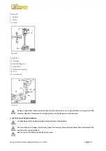
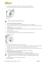
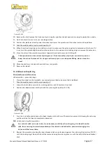
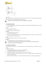
Move
the
tool
holder
arm
away
from
the
rim
edge.
Release
the
ratchet
and
lift
the
arm
to
the
non
‐
working
position.
Move
the
tool
holder
arm
to
the
inner
side
of
the
wheel.
9.
Press
the
tool
rotation
lever
and
turn
it
180°;
the
tool
will
automatically
lock.
Lower
the
arm
to
the
working
position.
10.
Take
the
mobile
control
unit
to
work
position
D.
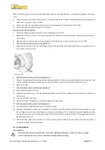
11.
Turn
the
turntable
and
lower
it
at
the
same
time
in
order
to
insert
the
bead
breaker
disk
between
the
bead
and
the
rim
edge.
Only
when
the
bead
starts
to
detach,
move
the
disk
forward
until
positioning
the
external
bead
flush
with
the
external
rim
edge.
N.B.:
lubricate
during
this
operation.
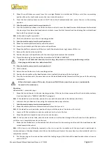
12.
Tilt
the
tool
holder
arm
to
the
non
‐
working
position.
13.
Take
the
mobile
control
unit
to
work
position
B.
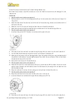
14.
Move
the
mobile
platform
directly
under
the
wheel.
15.
Lower
the
turntable
until
the
tyre
rests
on
the
platform.
16.
Move
the
platform
outward
until
the
tyre
(with
the
attached
side
ring)
comes
off
the
rim.
17.
Remove
the
rim
from
the
turntable.
18.
Position
the
tyre
on
the
platform
with
the
side
ring
turned
towards
the
turntable.
19.
Clamp
the
side
ring
on
the
turntable
as
described
for
“WHEEL
CLAMPING”.
The
tyre
is
not
fastened
securely
to
side
ring.
Any
strain
on
it
during
positioning
and/or
clamping
could
cause
it
to
detach
and
fall.
20.
Take
the
mobile
control
unit
to
work
position
D.
21.
Lift
the
wheel.
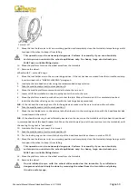
22.
Return
the
tool
holder
arm
to
the
working
position.
23.
Position
the
turntable
so
the
bead
breaker
disk
is
perfectly
lined
up
with
the
tyre
bead.
24.
Turn
the
turntable
and
at
the
same
time
move
the
bead
breaker
disk
forward
until
the
tyre
exits
the
side
ring
completely.
When
the
beads
come
off
the
rim,
the
tyre
will
fall.
Make
sure
that
no
one
is
accidentally
located
in
the
work
area.
Mounting
Wheels
with
3
–
piece
side
rings
1.
Move
the
turntable
arm
to
the
non
‐
working
position.
If
the
rim
has
been
removed
from
the
turntable,
reclamp
it
as
described
in
the
“WHEEL
CLAMPING”
paragraph.
N.B.:
if
the
wheel
has
an
inner
tube,
position
the
rim
with
the
valve
slot
at
the
bottom
(6
o’clock).
2.
Lubricate
the
tyre
beads
and
rim
using
the
recommended
soapy
solution.
3.
Take
the
mobile
control
unit
to
work
position
B.
4.
Move
the
mobile
platform
outward
in
order
to
place
the
tyre
on
it.
N.B.:
if
the
wheel
has
an
inner
tube,
position
the
tyre
with
the
valve
at
the
bottom
(6
o’clock).
5.
Lower
or
lift
the
turntable
in
order
to
exactly
center
the
rim
to
the
tyre.
6.
Move
the
platform
inward
to
make
the
rim
enter
the
tyre.
N.B.:
if
the
tyre
has
an
inner
tube,
push
the
valve
inside
so
it
will
not
be
damaged.
Move
forward
with
the
platform
until
the
rim
is
completely
inserted
in
the
tyre.
7.
Move
the
tool
holder
arm
to
the
external
side
then
lower
it
to
the
working
position
with
the
bead
breaker
disk
turned
towards
the
wheel.
N.B.:
if
the
tyre
is
not
sufficiently
inserted
on
the
rim,
move
the
turntable
until
the
tyre
bead
is
positioned
in
correspondence
of
the
bead
breaker
disk.
Move
the
disk
forward
(and
at
the
same
time
turn
the
turntable)
until
it
is
completely
inserted.
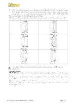
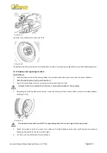
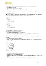
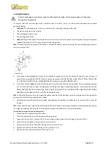
8.
Put
the
side
ring
on
the
rim
and
then
install
the
locking
ring
with
the
help
of
the
bead
breaker
disk
as
shown
in
picture
F13.27.
Summary of Contents for FT 26S
Page 2: ......
Page 6: ......
Page 33: ...Manuale Manual Manuel Handbuch Manual 07 2014 Pagina 27 19 SCHEMA ELETTRICO...
Page 34: ...Manuale Manual Manuel Handbuch Manual 07 2014 Pagina 28 20 SCHEMA IDRAULICO...
Page 35: ...Manuale Manual Manuel Handbuch Manual 07 2014 Pagina 29...
Page 61: ...Manuale Manual Manuel Handbuch Manual 07 2014 Pagina 55 19 ELECTRICAL DIAGRAM...
Page 62: ...Manuale Manual Manuel Handbuch Manual 07 2014 Pagina 56 20 HYDRAULIC DIAGRAM...
Page 63: ...Manuale Manual Manuel Handbuch Manual 07 2014 Pagina 57...
Page 89: ...Manuale Manual Manuel Handbuch Manual 07 2014 Pagina 83 19 SCHEMA ELECTRIQUE...
Page 90: ...Manuale Manual Manuel Handbuch Manual 07 2014 Pagina 84 20 SCHEMA HYDRAULIQUE...

