Manuale/Manual/Manuel/Handbuch/Manual
–
07/2014
Pagina
37
12.
CORRECT
OPERATIONS
CHECKS
Before
using
the
tyre
changer,
a
number
of
checks
should
be
made
to
ensure
it
works
correctly.
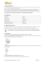
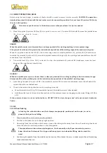
CAUTION:
The
operations
described
here
should
be
done
with
the
tool
carrier
arm
in
its
non
‐
working
position.
First,
use
lever
(15,
picture
F8.3)
to
tip
the
arm
to
this
position.
Do
not
move
your
face
close
to
the
tool
carrier
arm
when
you
release
it
to
tip
it
as
needed.
1.
Move
the
joystick
(8,
picture
F8.2)
up
(A):
the
spindle
carrier
arm
(2,
picture
F8.1)
should
lift;
move
the
joystick
down
(B):
t h e
a r m
s h o u l d
l o w e r ;
DANGER!
When
the
spindle
carrier
arm
is
lowered
there
is
always
a
potential
for
crushing
anything
in
its
movement
range.
Always
work
from
the
position
given
in
the
instructions
keep
well
out
of
the
working
range
of
the
various
moving
arms.
Move
the
joystick
towards
the
left
(C):
the
tool
carriage
and
the
mobile
platform
(13,
picture
F8.3)
should
move
towards
the
spindle
(3,
picture
F8.1);
move
the
joystick
towards
the
right
(D):
the
carriage
tool
and
platform
should
move
away
from
the
spindle.
2.
Turn
switch
lever
(9,
picture
F8.2)
towards
the
top:
the
spindle
arms
(3,
picture
F8.1)
should
open;
move
the
lever
down
and
the
spindle
arms
should
close.
DANGER!
When
the
spindle
arms
open
or
closed,
there
is
always
a
potential
for
crushing
anything
in
their
movement
range.
Always
work
from
the
position
given
in
the
instructions
keep
well
out
of
the
spindle’s
working
range.
3.
Press
the
right
pedal
(10,
picture
F8.2):
the
spindle
(3,
picture
F8.1)
should
turn
clockwise;
press
the
left
pedal:
the
spindle
should
turn
anticlockwise.
4.
Check
to
be
certain
the
hydraulic
circuit
is
working
correctly:
Move
the
switch
lever
(9,
Fig.
F8.2)
towards
the
top
until
the
spindle
arms
are
fully
extended.
Hold
the
switch
lever
in
this
position
(top)
and
check
if
the
pressure
shown
on
the
gauge
on
the
swivel
fitting
is
130
Bar
±5%.
If
the
pressure
shown
in
not
as
indicated
here,
DO
NOT
USE
the
tyre
changer
and
call
your
nearest
Assistance
Centre
.
13.
USE
13.1
Wheel
locking
In
locking
the
wheel
make
sure
that
clamps
are
properly
positioned
on
the
rim,
so
as
to
prevent
the
tyre
from
falling.
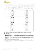
1.
Take
the
mobile
control
unit
to
work
position
B.
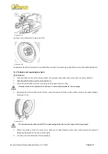
2.
Pull
the
tool
‐
holder
arm
into
the
up
‐
right
position.
3.
Operating
from
the
mobile
control
center,
move
the
sliding
table
away
from
the
self
‐
centering
chuck
and
place
the
wheel
in
vertical
position
on
the
sliding
table.
This
operation
can
be
extremely
dangerous.
Do
it
manually
only
if
you
are
certain
you
can
keep
the
wheel
balanced.
For
large
and
heavy
tyres
an
adequate
lifting
device
must
be
used.
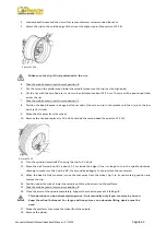
4.
Continuing
to
operate
from
the
mobile
control
center,
lift
or
lower
the
arm
in
order
center
the
self
‐
centering
chuck
relative
to
the
rim.
Summary of Contents for FT 26S
Page 2: ......
Page 6: ......
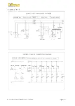
Page 33: ...Manuale Manual Manuel Handbuch Manual 07 2014 Pagina 27 19 SCHEMA ELETTRICO...
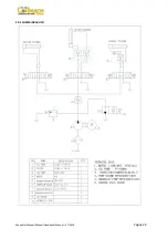
Page 34: ...Manuale Manual Manuel Handbuch Manual 07 2014 Pagina 28 20 SCHEMA IDRAULICO...
Page 35: ...Manuale Manual Manuel Handbuch Manual 07 2014 Pagina 29...
Page 61: ...Manuale Manual Manuel Handbuch Manual 07 2014 Pagina 55 19 ELECTRICAL DIAGRAM...
Page 62: ...Manuale Manual Manuel Handbuch Manual 07 2014 Pagina 56 20 HYDRAULIC DIAGRAM...
Page 63: ...Manuale Manual Manuel Handbuch Manual 07 2014 Pagina 57...
Page 89: ...Manuale Manual Manuel Handbuch Manual 07 2014 Pagina 83 19 SCHEMA ELECTRIQUE...
Page 90: ...Manuale Manual Manuel Handbuch Manual 07 2014 Pagina 84 20 SCHEMA HYDRAULIQUE...

