Manuale/Manual/Manuel/Handbuch/Manual
–
07/2014
Pagina
40
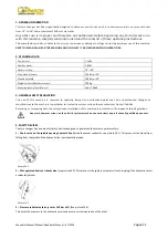
To
facilitate
this
operation,
lubricate
the
bead
and
the
edge
of
the
rim
with
tyre
lubricant
whilst
the
wheel
is
rotated.
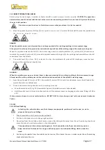
To
avoid
all
risk,
lubricate
the
beads
turning
the
wheel
clockwise
if
you
are
working
on
the
outside
plane
and
anticlockwise
if
working
on
the
inside
plane.
N.B.:
remember
that
the
stronger
the
tyre’s
adherence
to
the
rim,
the
slower
must
be
the
disk’s
penetration.
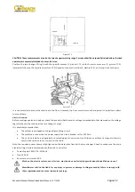
7.
Bring
the
tool
carrier
arm
back
from
the
edge
of
the
rim.
Release
the
hook,
raise
the
arm
to
its
non
‐
working
position,
shift
it
and
rehook
it
in
its
second
work
position
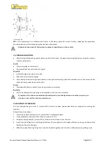
(Picture
F13.10).
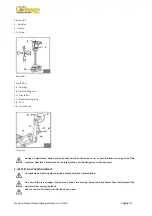
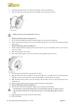
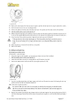
Picture
F13.10
Do
not
hold
your
hands
on
the
pool
when
you
bring
it
back
to
its
work
position.
Your
hands
could
be
trapped
between
the
tool
and
the
wheel.
8.
Push
the
double
headed
tool
lever
(B,
picture
F13.10)
and
turn
the
head
180°
until
it
locks
automatically.
9.
Take
the
mobile
control
unit
to
work
position
D.
10.
Repeat
the
operation
previously
described
until
the
second
bead
is
completely
broken.
N.B.
:
during
the
bead
‐
breaking,
the
claw
(A,
picture
F13.10)
can
be
lowered
so
that
it
is
out
of
the
way.
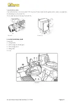
Demounting
Tubeless
tyre
can
be
demounted
in
two
ways:
a)
If
the
tyre
is
not
difficult
to
demount,
once
the
beads
have
been
loosened,
use
the
bead
disk
to
push
against
the
inside
plane
of
the
tyre
until
both
beads
come
off
the
rim
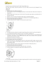
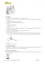
(See
picture
F13.11).
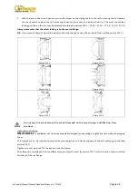
Picture
F13.11
b)
With
SUPERSINGLE
or
very
hard
tyres
the
procedure
described
above
cannot
be
used.
The
hook
tool
will
have
to
be
used
as
follows:
1.
Transfer
the
tool
carrier
arm
to
the
outside
plane
of
the
tyre.
2.
Take
the
mobile
control
unit
to
work
position
C.
3.
Rotate
the
wheel
and
at
the
same
time
move
the
hook
tool
forward
inserting
it
between
rim
and
bead
until
it
is
anchored
to
the
bead
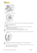
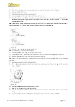
(See
picture
F13.12).
A
B
Summary of Contents for FT 26S
Page 2: ......
Page 6: ......
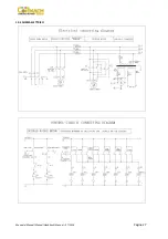
Page 33: ...Manuale Manual Manuel Handbuch Manual 07 2014 Pagina 27 19 SCHEMA ELETTRICO...
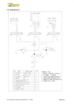
Page 34: ...Manuale Manual Manuel Handbuch Manual 07 2014 Pagina 28 20 SCHEMA IDRAULICO...
Page 35: ...Manuale Manual Manuel Handbuch Manual 07 2014 Pagina 29...
Page 61: ...Manuale Manual Manuel Handbuch Manual 07 2014 Pagina 55 19 ELECTRICAL DIAGRAM...
Page 62: ...Manuale Manual Manuel Handbuch Manual 07 2014 Pagina 56 20 HYDRAULIC DIAGRAM...
Page 63: ...Manuale Manual Manuel Handbuch Manual 07 2014 Pagina 57...
Page 89: ...Manuale Manual Manuel Handbuch Manual 07 2014 Pagina 83 19 SCHEMA ELECTRIQUE...
Page 90: ...Manuale Manual Manuel Handbuch Manual 07 2014 Pagina 84 20 SCHEMA HYDRAULIQUE...

