background image


Manuale/Manual/Manuel/Handbuch/Manual


07/2014


Pagina


32


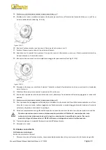
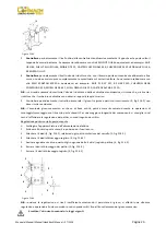
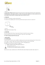
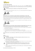
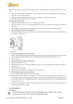
Picture


F4.3


4


Pump


motor


overload


cut

out


(inside


the


electric


enclosure).


This


cuts


in


if


the


motor


overheats


to


prevent


it


from


burning


out.


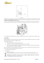
CAUTION:


Removing


or


tampering


with


safeties


is


in


violation


of


European


Safety


Regulations


and


relieves


manufacturer


of


any


and


all


liability


for


injury


to


persons


to


damage


to


things


caused


or


referable


to


such


acts.


5.


TRANSPORT


The


machine


is


delivered


in


a


wooden


crate


with


pallet.


The


machine


must


be


handled


with


a


fork

lift


truck


with


the


forks


positioned


as


shown


in


the


picture


F5.1.


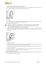
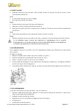
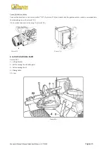
Picture


F5.1


Shipping


weight


for


the


machine


is


775


Kg.


6.


UNPACKING


Once


the


packing


material


has


been


removed,


check


the


machine


visually


for


any


signs


of


damage.


Keep


the


packing


materials


out


of


the


reach


of


children


as


they


can


be


a


source


of


danger.


N.B.:


Keep


the


packing


for


possible


future


transport.


7.


INSTALLATION


7.1


Installation


place


Choose


the


place


the


machine


is


to


be


installed


in


compliance


with


current


work


place


safety


regulations.


The


floor


should


not


be


broken


or


uneven


so


that


the


machine


will


be


stable


and


the


platform


rollers


can


move


freely.


If


the


installation


is


outdoor,


it


must


be


protected


by


some


kind


of


roofing


against


rain.


The


following


work


environment


conditions


are


applicable:


Relative


humidity


from


30%


to


95%


without


condensation;


Temperature


from


to


55°


C.


The


machine


must


not


be


operated


in


explosive


atmospheres.


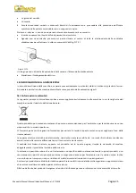
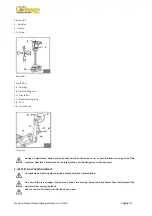
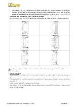
Maximum


machine


space


requirements


are


mm.


2085


x


1820,


with


a


minimum


distance


from


walls


as


shown


in


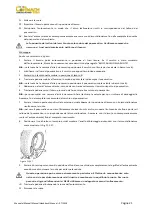
picture


F7.1.


Summary of Contents for FT 26S

Page 1: ...SMONTAGOMME TYRE CHANGER DEMONTE PENUS FT 26S 07 2014 MANUALE USO E MANUTENZIONE USE AND MAINTENANCE MANUAL MANUEL D UTILISATION ED D ENTRETIEN IT UK FR...

Page 2: ......

Page 3: ...2006 42 EC Machinery Directive MD 91 368 CEE 93 68 CEE 2006 95 CE 2004 108 CE Directive 2006 42 EC Directive Machines MD 91 368 CEE 93 68 CEE 2006 95 CE 2004 108 CE Richtlinie 2006 42 EC Maschinenric...

Page 4: ...de ses composants doit tre effectu e la conformit aux Directive suivante Verschrottung mu gem der folgenden Vorschrift durchgef hrt werden 2002 96 CE e and et und 2003 108 CE RAEE E le disposizioni d...

Page 5: ...ubject to sanctions according to the national Laws of the Country of destination Abandonment or wrong scrapping of the equipment subject to Directive 2002 96 CE can cause serious damage to the environ...

Page 6: ......

Page 7: ...E COMANDI 11 POSIZIONE DI LAVORO 12 CONTROLLO CORRETTO FUNZIONAMENTO 13 USO 13 1 Bloccaggio ruota 13 2 Ruote tubeless e Supersingle 13 3 Ruote con camera d aria 13 4 Ruota con cerchietto 14 MANUTENZIO...

Page 8: ...A 3 NORME GENERALI DI SICUREZZA L uso dell apparecchiatura consentito solo a personale appositamente addestrato ed autorizzato Qualsiasi manomissione o modifica dell apparecchiatura non preventivament...

Page 9: ...llaggio assicurarsi dell integrit della macchina controllando che non vi siano parti visibilmente danneggiate Gli elementi dell imballaggio non devono essere lasciati alla portata dei bambini in quant...

Page 10: ...mente che la tensione di rete corrisponda con quanto riportato sul cartellino voltaggio posizionato in prossimit della spina dello smontagomme E assolutamente obbligatorio che L impiantosia corredatod...

Page 11: ...rotazione del motore della centralina oleodinamica sia quello indicato dalla freccia 6 fig F7 3 In caso contrario fare invertire tra loro da personale specializzato due fili nella spina 7 fig F7 4 Fi...

Page 12: ...ni e le altre parti del corpo il pi lontano possibile dalle parti in movimento Collane braccialetti abiti non aderenti possono costituire pericolo per chi opera 9 IDENTIFICAZIONE SEGNALI DI PERICOLO N...

Page 13: ...ll autocentrante SBLOCCA Il pedale a bilanciere 10 fig F8 2 consente se azionato in uno dei due lati di far ruotare l autocentrante in un senso o nell altro come indicato dalle frecce poste sulla peda...

Page 14: ...ono allontanarsi dall autocentrante 2 Azionare l interruttore 9 Fig F8 2 verso l alto i bracci dell autocentrante 3 Fig F8 1 devono aprirsi azionare l interruttore verso il basso i bracci dell autocen...

Page 15: ...F13 1 F13 2 F13 3 F13 4 F13 5 F13 6 Si ricorda che il bloccaggio sulla flangia centrale da ritenersi sempre il pi sicuro N B per le ruote con il cerchio a canale bloccare la ruota in modo che il cana...

Page 16: ...rettamente agganciato al carrello 4 Agendo sul manipolatore posizionare la ruota in modo che il profilo esterno del cerchio sfiori il disco stallonatore Fig F13 9 Figura F13 9 Il disco stallonatore no...

Page 17: ...no al completo distacco del secondo tallone N B durante la stallonatura l utensile a becco A fig F13 10 pu essere abbassato in modo da non costituire ostacolo Smontaggio Lo smontaggio di pneumatici tu...

Page 18: ...mobile in posizione di lavoro D 12 Girare l utensile a becco di 180 inserire il medesimo tra cerchio e tallone Vedi fig F13 13 e traslarlo fino a che il tallone sia in prossimit del bordo anteriore d...

Page 19: ...nel punto pi alto per agganciare il primo tallone alla pinza stessa 6 Sollevare il cerchio con il pneumatico agganciato e ruotarlo in senso antiorario di 15 20 cm Il pneumatico si posizioner in modo o...

Page 20: ...stallonatore 2 Portare il braccio porta utensili in posizione di fuori lavoro traslarlo sul fianco interno del pneumatico e riagganciarlo in questa posizione 3 Verificare che l utensile a becco sia p...

Page 21: ...rante e contemporaneamente fare avanzare l utensile a becco inserendolo tra cerchio e tallone fino a che quest ultimo si sar agganciato all utensile 4 Allontanare di circa 4 5 cm il cerchio dall utens...

Page 22: ...Montaggio 1 Se il cerchio stato smontato dall autocentrante bloccarlo nuovamente come descritto nel paragrafo BLOCCAGGIO DELLA RUOTA 2 Lubrificare i talloni del pneumatico e cerchio con apposita soluz...

Page 23: ...ta mobile in posizione di lavoro B 18 Ruotare l autocentrante fino a portare il foro della valvola in basso a ore 6 19 Portare la pedana mobile sulla verticale della ruota ed abbassare l autocentrante...

Page 24: ...ana sotto la verticale della ruota abbassare l autocentrante fino ad appoggiare la ruota sulla pedana 33 Portarsi con la colonnetta mobile in posizione di lavoro B 34 Con il pneumatico appoggiato sull...

Page 25: ...razione facendo per avanzare il disco stallonatore contro il cerchietto Vedi fig F13 25 fino a liberare l anello di bloccaggio che verr poi estratto con l apposita leva per cerchietti o con l aiuto de...

Page 26: ...il braccio porta utensili dal bordo del cerchio Sganciare il cricchetto e sollevare il braccio in posizione di fuori lavoro Traslare il braccio porta utensili sul lato interno della ruota 9 Premere la...

Page 27: ...alzare l autocentrante in modo da centrare esattamente il cerchio rispetto al pneumatico 6 Traslare la pedana verso l interno in modo da fare entrare il cerchio nel pneumatico N B per pneumatici con c...

Page 28: ...netta mobile in posizione di lavoro B 12 Posizionare sul cerchio l anello di bloccaggio aiutandosi con il disco stallonatore come mostrato in fig F13 27 13 Portare il braccio porta utensili in posizio...

Page 29: ...carrello orizzontale il gioco fra guide e pattini di scorrimento 5 fig F14 2 non deve risultare evidente N B l eventuale gioco meccanico anche se di lieve entit potr essere riscontrato durante le oper...

Page 30: ...gomme e chiamare immediatamente il servizio tecnico di assistenza 16 MOVIMENTAZIONE Lo smontagomme dispone di una staffa 1 fig F16 1 appositamente sistemata per effettuare la movimentazione della macc...

Page 31: ...hina riporta il simbolo del bidone barrato Questo prodotto pu contenere sostanze che possono essere dannose per l ambiente e per la salute umana se non viene smaltito in modo opportuno Vi forniamo per...

Page 32: ...to viene smaltito Vi raccomandiamo inoltre di adottare altri provvedimenti favorevoli all ambiente riciclare l imballo interno ed esterno con cui il prodotto fornito e smaltire in modo adeguato le bat...

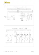
Page 33: ...Manuale Manual Manuel Handbuch Manual 07 2014 Pagina 27 19 SCHEMA ELETTRICO...

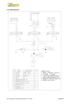
Page 34: ...Manuale Manual Manuel Handbuch Manual 07 2014 Pagina 28 20 SCHEMA IDRAULICO...

Page 35: ...Manuale Manual Manuel Handbuch Manual 07 2014 Pagina 29...

Page 36: ...11 WORKING POSITION 12 CORRECT OPERATIONS CHECK 13 USE 13 1 Wheel locking 13 2 Tubeless and Supersingle wheels 13 3 Tubed wheels 13 4 Wheels with split ring 14 MAINTENANCE 15 TROUBLE SHOOTING 16 MOVIN...

Page 37: ...is machine is reserved to specially trained and authorized personnel Any unauthorized changes or modifications to the machine in particular to its electric system relieve the manufacturer from all lia...

Page 38: ...erial has been removed check the machine visually for any signs of damage Keep the packing materials out of the reach of children as they can be a source of danger N B Keep the packing for possible fu...

Page 39: ...stamped on the voltage tag attached to the cord near the tyre changer s plug It is absolutely essential that The system is equipped with a good grounding circuit The machine is connected to a power s...

Page 40: ...re F7 4 and check that the gearbox motor rotation corresponds to the indicating arrow 6 picture F7 3 If not switch two wires in the plug 7 picture F7 4 Picture F7 3 Picture F7 4 8 LAYOUT FUNCTIONAL PA...

Page 41: ...nds and other parts of the body as far as possible from moving parts of the machine Necklaces bracelets and too large clothes can be dangerous for the operator 9 IDENTIFYING WARNING SIGNALS Unreadable...

Page 42: ...ses the arm of the self centering chuck UNLOCKING The pedal 10 picture F8 2 when pressed on the left or right side rotates the self centering chuck in the same direction as shown by the arrows placed...

Page 43: ...or closed there is always a potential for crushing anything in their movement range Always work from the position given in the instructions keep well out of the spindle s working range 3 Press the ri...

Page 44: ...annel is near the outside of the rim See picture F13 1 Picture F13 1 Picture F13 2 Picture F13 3 Picture F13 4 Picture F13 5 Picture F13 6 Do not very the work area with a wheel clamped on the tyre ch...

Page 45: ...mobile control unit to work position C 3 Lower the tool holder arm into is working position and allow it to lock Always check to be certain that the arm is corrected hooked to the carriage 4 Operatin...

Page 46: ...le headed tool lever B picture F13 10 and turn the head 180 until it locks automatically 9 Take the mobile control unit to work position D 10 Repeat the operation previously described until the second...

Page 47: ...the rim best to do this with the wheel turning Picture F13 13 13 Move the rim about 4 5 cm from the tool making sure the hook does not deattach from the rim 14 Take the mobile control unit to work pos...

Page 48: ...l 10 Remove the clip and replace it at 6 o clock outside the second bead See picture F13 15 Picture F13 15 11 Turn the spindle clockwise 90 to bring the clip to 9 o clock 12 Move the disk forward unti...

Page 49: ...ct position of the hook visually and adjust it as needed Then turn the spindle clockwise until the clip is at the bottom 6 o clock The first bead will be on the rim 8 Remove the clip 9 Take the mobile...

Page 50: ...of the rim about 5 mm from the hooked tool 9 Turn the wheel anticlockwise pressing down on lever until the bead is completely off 10 Move the tool carrier arm to its non working position Lower the spi...

Page 51: ...rim with the tyre hook to it and turn it anticlockwise about 15 20 cm The tyre will be positioned tilted across the rim 7 Move the tool carrier arm to its non working position Move it to the inside p...

Page 52: ...inner tube in the center well of the rim N B to facilitate this turn the spindle clockwise 21 Turn the spindle until the valve is at the bottom 6 o clock 22 Inflate the inner tube a little until it ha...

Page 53: ...d 36 Move the platform to release the wheel from the spindle 37 Remove the wheel 13 4 Wheels with split ring Bead breaking and demounting Wheels with 3 piece side rings 1 Clamp the wheel on the turnta...

Page 54: ...ectly under the tyre 13 Lower the tunrtable until the tyre rests on the platform 14 Take the mobile control unit to work position B 15 Move the platform outward until the tyre is completely removed fr...

Page 55: ...ead breaker disk is perfectly lined up with the tyre bead 24 Turn the turntable and at the same time move the bead breaker disk forward until the tyre exits the side ring completely When the beads com...

Page 56: ...e ring have slits for fixing devices make sure they are lined up with each other 8 Take the mobile control unit to work position C 9 Move the tool holder arm to the external side then lower it to the...

Page 57: ...ck the oil level in the gear unit which when the tool carrier brackets is completely lowered at end travel should not show the sight glass on the gear casing as completely empty If necessary top up wi...

Page 58: ...r pack does not function Causes The magneto thermic switch for motor protection is working Remedies Call for technical aid to see what is the problem and restore the machine If inspite of the above me...

Page 59: ...internal working parts If the machine as to working again after a long storing period it is necessary to Put the oil into the reservoirs again With a turnscrew press the pin on the middle of the elect...

Page 60: ...facturers and distributors set up proper collection and treatment systems for these products for this purpose At the end of the product s working life contact your supplier for information about dispo...

Page 61: ...Manuale Manual Manuel Handbuch Manual 07 2014 Pagina 55 19 ELECTRICAL DIAGRAM...

Page 62: ...Manuale Manual Manuel Handbuch Manual 07 2014 Pagina 56 20 HYDRAULIC DIAGRAM...

Page 63: ...Manuale Manual Manuel Handbuch Manual 07 2014 Pagina 57...

Page 64: ...TION DE TRAVAIL 12 CONTROL DU BON FONCTIONNEMENT 13 UTILISATION 13 1 Blocage de la roue 13 2 Roues tubeless et supersingle 13 3 Roues avec chambre air 13 4 Roues avec tringle 14 ENTRETIEN 15 INCONVENI...

Page 65: ...u poste de travail LpA 70 dbA 3 NORMES GENERALES DE SECURITE L utilisation de l appareillage est r serv e au personnel sp cialement form et autoris Toute manipulation ou modification de l appareillage...

Page 66: ...ballage s assurer du bon tat de la machine en v rifiant qu il n y a pas de parties visiblement endommag es Les l ments de l emballage ne doivent pas tre laiss s la port e des enfants car ils repr sent...

Page 67: ...sion du r seau d alimentation correspond celle indiqu e sur la plaquette de voltage plac e proximit de la fiche du d monte pneus Il est absolument obligatoire que Le circuit soit quip d un bon r seau...

Page 68: ...teur de la centrale hydrodynamique correspond celui qui est indiqu par la fl che 6 fig F7 3 Dans le cas contraire faire intervenir du personnel sp cialis pour inverser les deux fils dans la fiche 7 fi...

Page 69: ...rties du corps le plus loin possible des parties en mouvement Les colliers bracelets v tements flottants peuvent constituer un danger pour l op rateur 9 IDENTIFICATION DES SIGNAUX DE DANGER Si les pla...

Page 70: ...OCAGE s il est actionn vers le bas La p dale balancier 10 fig F8 2 permet la rotation du mandrin dans un sens ou dans l autre indiqu par les fl ches plac es sur le p dalier NOTE toutes les commandes s...

Page 71: ...actionner l interrupteur vers le bas les bras du mandrin doivent se fermer ATTENZIONE Les op rations d ouverture et de fermeture du mandrin cr ent des points d crasement potentiels Travailler exclusiv...

Page 72: ...e jante Voir les figures F13 1 F13 2 F13 3 F13 4 F13 5 F13 6 Sachez que le blocage sur le plateau central est toujours plus s r N B pour les jantes gorge bloquer la roue de mani re ce que le creux se...

Page 73: ...oit accroch au cliquet correspondant V rifier toujours si le bras est bien accroch au chariot 4 En agissant sur le manipulateur placer la roue de fa on ce que le profil externe de la jante effleure le...

Page 74: ...e 180 qui se bloquera automatiquement 9 Placer la colonnette mobile en position de travail D 10 R p ter les op rations des tapes 5 et 6 pr c dentes jusqu d collement complet du deuxi me talon N B pend...

Page 75: ...n Voir fig F13 13 en le faisant avancer jusqu ce que le talon soit pr s du bord avant de la jante il est conseill d effectuer cette op ration en tournant simultan ment la roue Figure F13 13 13 Eloigne...

Page 76: ...C 8 Placer le disque d talonneur contre le deuxi me talon du pneu et tourner le mandrin jusqu amener la pince le plus bas possible 6 heures 9 Eloigner le disque d talonneur de la roue 10 Enlever la pi...

Page 77: ...gative appuyer sur le levier sur le levier de rotation de l outil et tourner de 180 4 Placer la colonnette mobile en position de travail D 5 Avancer l outil jusqu placer son rep re rouge dans l axe d...

Page 78: ...onnette mobile en position de travail B 7 Introduire le d colle talon Voir fig F13 17 entre la jante et talon sur la droite de l outil Figure F13 17 8 Appuyer sur le d colle talon tout en abaissant la...

Page 79: ...oir fig F13 19 Figure F13 19 V rifier si la pince est bien accroch e la jante 4 Placer la colonnette mobile en position de travail B 5 Placer le pneu sur la plate forme et abaisser le mandrin en veill...

Page 80: ...a plate forme vers l ext rieur de fa on cr er de la place entre le pneu et la jante dans laquelle introduire la chambre air N B le trou de la valve peut se trouver dans une position asym trique par ra...

Page 81: ...r si la valve est parfaitement align e avec le trou de sortie Dans la n gative tourner l g rement le mandrin de fa on en ajuster la position Fixer la valve avec la bague et retirer la rallonge 35 Ferm...

Page 82: ...pour tringles ou avec le disque d talonneur Figure F13 25 7 Enlever la tringle 8 Eloigner le bras porte outils du bord de la jante D crocher le cliquet et lever le bras en position de hors travail D p...

Page 83: ...le en position de travail D 11 Tourner le mandrin et l abaisser de fa on introduire le disque d talonneur entre le talon et le bord de la jante N B lubrifier pendant l op ration 12 Placer le bras port...

Page 84: ...fermer compl tement les griffes du mandrin en ayant soin de soutenir la roue pour ne pas qu elle tombe Cette op ration peut se r v ler extr mement dangereuse Ne l effectuer manuellement que si l on es...

Page 85: ...e pas gonfler le pneu avec la roue encore mont e sur le mandrin Le gonflage des pneus est une op ration risque il doit donc tre effectu en enlevant la roue du mandrin et en l introduisant dans les cag...

Page 86: ...chariot porte outils 1 D brancher l appareil de l alimentation lectrique 2 Soulever le bras porte outils dans la position hors travail 3 Desserrez les 4 crous 1 fig F14 2 de chaque patin inf rieur du...

Page 87: ...age largeur minimum 60 mm et longueur suffissante pour se placer au dessus du d monte pneus 6 Avec l anneau de la sangle r unir les deux bouts et soulever avec un engin appropri Figure F16 1 17 REMISA...

Page 88: ...ri des substances qu il contient ou qu un traitement incorrect d une partie de celles ci puisse avoir des cons quences graves sur l environnement et la sant de l homme Une gestion correcte du produit...

Page 89: ...Manuale Manual Manuel Handbuch Manual 07 2014 Pagina 83 19 SCHEMA ELECTRIQUE...

Page 90: ...Manuale Manual Manuel Handbuch Manual 07 2014 Pagina 84 20 SCHEMA HYDRAULIQUE...

Page 91: ...e FR Cormach s r l nous nous r servons le droit d apporter des modifications ses produits pour les am liorer Cormach s r l Nous nous r servons le droit d apporter des modifications ce manuel sans pr a...

Page 92: ...CORMACH S r l via A Pignedoli 2 42015 CORREGGIO RE ITALY Tel 39 0522 631274 Fax 39 0522 631284 e mail cormach cormachsrl com www cormachsrl com...

Reviews: