Manuale/Manual/Manuel/Handbuch/Manual
–
07/2014
Pagina
36
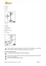
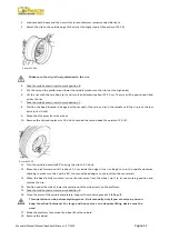
Picture
F9.1
10.
IDENTIFYING
CONTROLS
The
mobile
control
center
(picture
F8.2)
enables
the
operator
to
work
at
any
position
around
the
machine.
On
this
mobile
control
center
the
following
controls
are
located:
The
lever
(8,
picture
F8.2)
which
in
position
“a”
lifts
the
chuck
arm
and
in
position
“b”
lowers
it;
in
position
“c”
moves
the
tool
holder
arm
and
the
sliding
table
towards
the
self
‐
centering
chuck
and
in
position
“d”
moves
them
away
(Note:
in
order
to
memorize
this
operation,
there
is
a
hole
in
the
lever
guard
corresponding
to
“c”).
The
chuck
switch
(9,
picture
F8.2)
when
moved
up
‐
wards,
opens
the
arms
of
the
self
‐
centering
chuck
(LOCKING);
and
when
moved
down
closes
the
arm
of
the
self
‐
centering
chuck
(UNLOCKING).
The
pedal
(10,
picture
F8.2)
when
pressed
on
the
left
or
right
side
rotates
the
self
‐
centering
chuck
in
the
same
direction
as
shown
by
the
arrows
placed
on
the
foot
pedal.
NOTE
:
all
the
controls
are
very
sensitive
and
small
movements
of
the
machine
can
be
done
with
precision.
The
tyre
changer
also
has:
Lever
(15,
picture
F8.3)
to
tip
the
tool
carrier
arm
(14,
picture
F8.3)
from
its
non
‐
working
position
and
vice
‐
versa.
Handle
(19,
picture
F8.3)
that
permits
alternative
use
of
the
bead
‐
breaking
disk
(17,
picture
F8.3)
or
the
hooked
tool
(18,
picture
F8.3).
11.
WORKING
POSITION
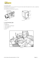
The
picture
F11.1
illustrates
the
various
working
positions
(A,
B,
C,
D)
referred
to
in
the
following
pages
describing
how
to
use
the
tyre
changer.
Use
of
these
positions
ensures
greater
precision,
speed
and
safety
for
those
using
the
machine.
Picture
F11.1
a
d
b
c
3014036
3014034
3014056
3014030
3014033
Summary of Contents for FT 26S
Page 2: ......
Page 6: ......
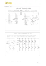
Page 33: ...Manuale Manual Manuel Handbuch Manual 07 2014 Pagina 27 19 SCHEMA ELETTRICO...
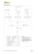
Page 34: ...Manuale Manual Manuel Handbuch Manual 07 2014 Pagina 28 20 SCHEMA IDRAULICO...
Page 35: ...Manuale Manual Manuel Handbuch Manual 07 2014 Pagina 29...
Page 61: ...Manuale Manual Manuel Handbuch Manual 07 2014 Pagina 55 19 ELECTRICAL DIAGRAM...
Page 62: ...Manuale Manual Manuel Handbuch Manual 07 2014 Pagina 56 20 HYDRAULIC DIAGRAM...
Page 63: ...Manuale Manual Manuel Handbuch Manual 07 2014 Pagina 57...
Page 89: ...Manuale Manual Manuel Handbuch Manual 07 2014 Pagina 83 19 SCHEMA ELECTRIQUE...
Page 90: ...Manuale Manual Manuel Handbuch Manual 07 2014 Pagina 84 20 SCHEMA HYDRAULIQUE...

