


Manuale/Manual/Manuel/Handbuch/Manual
–
07/2014
Pagina
33
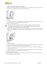
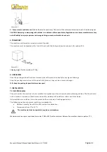
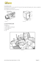
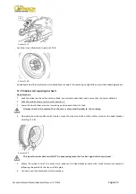
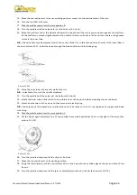
Picture
F7.1
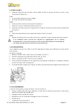
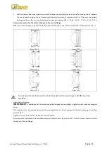
CAUTION:
These
measurements
are
also
the
tyre
changers
working
range.
Persons
other
than
especially
trained
and
authorized
operators
are
expressly
forbidden
to
enter
this
area.
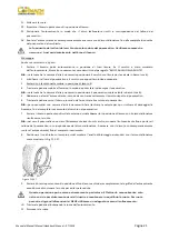
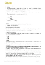
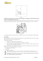
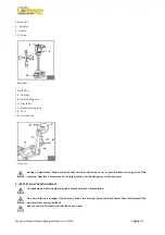
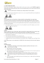
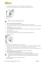
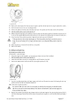
Position
the
tyre
changer
lifting
it
with
the
specific
bracket
(1,
picture
F7.2)
with
the
tool
carrier
arm
(2,
picture
F7.2)
lowered
all
the
way,
the
spindle
(3,
picture
F7.2)
closed
and
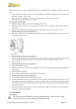
tool
carrier
slide
(4,
picture
F7.3)
at
its
stop
close
to
the
arm.
Picture
F7.2
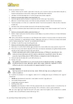
It
is
not
essential
to
anchor
the
machine
to
the
floor.
However,
the
floor
must
be
smooth
and
permit
the
platform
rollers
to
move
freely.
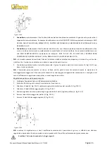
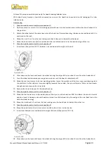
Electric
hook
‐
up
Before
making
any
electric
hook
‐
up,
check
to
be
certain
that
the
mains
voltage
corresponds
to
that
stamped
on
the
voltage
tag
(attached
to
the
cord
near
the
tyre
changer’s
plug).
It
is
absolutely
essential
that:
The
system
is
equipped
with
a
good
grounding
circuit.
The
machine
is
connected
to
a
power
supply
line
circuit
breaker
set
for
30
30
mA.
The
current
instake
is
adeguately
protected
against
overcurrents
with
fuses
or
automatic
magneto
‐
thermic
switch
with
rated
values
as
shown
in
the
table.
Note
the
required
power
draw
as
high
‐
lighted
on
the
data
plate
fixed
to
the
tyre
changer.
Check
to
make
sure
the
shop
electric
wiring
circuit
is
dimensioned
sufficiently
to
carry
this.
Power
Supply:
380V
‐
3Ph.
‐
50/60Hz
Fuse:
20A
AM
Remote
control
switch:
20A
Work
on
the
electric
system,
even
if
minor,
must
be
done
exclusively
by
professionally
qualified
personnel.
Manufacturer
shall
not
be
liable
for
any
injury
to
persons
or
damage
to
things
caused
by
failure
to
comply
with
these
regulations
and
can
cancel
warranty
coverage.
2500
mm
2500
mm
600
mm
1000
mm
Summary of Contents for FT 26S
Page 2: ......
Page 6: ......
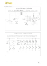
Page 33: ...Manuale Manual Manuel Handbuch Manual 07 2014 Pagina 27 19 SCHEMA ELETTRICO...
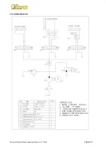
Page 34: ...Manuale Manual Manuel Handbuch Manual 07 2014 Pagina 28 20 SCHEMA IDRAULICO...
Page 35: ...Manuale Manual Manuel Handbuch Manual 07 2014 Pagina 29...
Page 61: ...Manuale Manual Manuel Handbuch Manual 07 2014 Pagina 55 19 ELECTRICAL DIAGRAM...
Page 62: ...Manuale Manual Manuel Handbuch Manual 07 2014 Pagina 56 20 HYDRAULIC DIAGRAM...
Page 63: ...Manuale Manual Manuel Handbuch Manual 07 2014 Pagina 57...
Page 89: ...Manuale Manual Manuel Handbuch Manual 07 2014 Pagina 83 19 SCHEMA ELECTRIQUE...
Page 90: ...Manuale Manual Manuel Handbuch Manual 07 2014 Pagina 84 20 SCHEMA HYDRAULIQUE...


