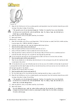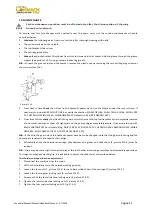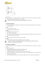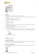
Manuale/Manual/Manuel/Handbuch/Manual
–
07/2014
Pagina
38
5.
With
the
jaws
in
the
closed
position,
move
the
wheel
on
the
sliding
table
to
the
self
‐
centering
chuck.
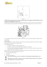
Operate
the
chuck
switch
to
open
the
self
‐
centering
chuck
and
lock
onto
the
inside
wheel
rim.
The
most
convenient
locking
position
on
the
rim
may
be
selected
according
to
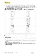
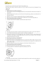
pictures
F13.1
–
F13.2
–
F13.3
–
F13.4
–
F13.5
–
F13.6.
Always
remember
that
the
safest
locking
is
on
the
central
flange.
N.B.:
for
rims
with
channel,
clamp
the
wheel
so
that
the
channel
is
near
the
outside
of
the
rim
(See
picture
F13.1).
Picture
F13.1
Picture
F13.2
Picture
F13.3
Picture
F13.4
Picture
F13.5
Picture
F13.6
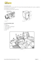
Do
not
very
the
work
area
with
a
wheel
clamped
on
the
tyre
changer
and
lifted
up
from
the
floor.
Light
‐
alloy
rim
locking
ON
REQUEST
,
is
available
a
set
of
clamps
especially
designed
for
operating
on
light
alloy
rims
without
damaging
them.
This
clamps
are
to
be
inserted
(bayonet
‐
like
mounting)
into
the
clamp
support
of
the
self
‐
centering
chuck
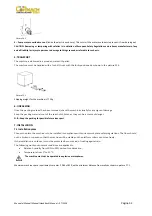
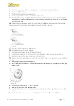
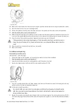
(See
pictureF13.7).
Tighten
screw
B,
picture
F13.7
by
hand
to
lock
the
clamp.
The
clamps
are
supplied
with
three
different
types
of
plastic
insert
(A,
picture
F13.7)
which
must
be
used
to
suit
the
thickness
of
the
rim
flange.
Summary of Contents for FT 26S
Page 2: ......
Page 6: ......
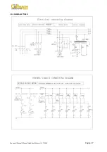
Page 33: ...Manuale Manual Manuel Handbuch Manual 07 2014 Pagina 27 19 SCHEMA ELETTRICO...
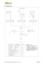
Page 34: ...Manuale Manual Manuel Handbuch Manual 07 2014 Pagina 28 20 SCHEMA IDRAULICO...
Page 35: ...Manuale Manual Manuel Handbuch Manual 07 2014 Pagina 29...
Page 61: ...Manuale Manual Manuel Handbuch Manual 07 2014 Pagina 55 19 ELECTRICAL DIAGRAM...
Page 62: ...Manuale Manual Manuel Handbuch Manual 07 2014 Pagina 56 20 HYDRAULIC DIAGRAM...
Page 63: ...Manuale Manual Manuel Handbuch Manual 07 2014 Pagina 57...
Page 89: ...Manuale Manual Manuel Handbuch Manual 07 2014 Pagina 83 19 SCHEMA ELECTRIQUE...
Page 90: ...Manuale Manual Manuel Handbuch Manual 07 2014 Pagina 84 20 SCHEMA HYDRAULIQUE...

