56
Epsilon EP-P Drive Reference Manual
www.controltechniques.com
Revision: A4
3.18
Devices / Vars Group
3.19
PLS View
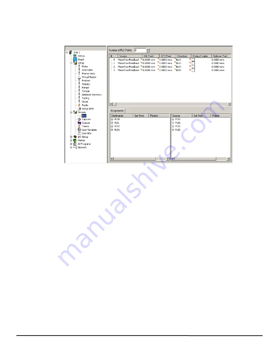
The PLS View allows users to define Programmable Limit Switches (PLS) for advanced machine operation. By selecting PLS in the Hierarchy
Tree, the PLS View will appear on the right (see Figure 59).
Figure 59:
PLS View
A PLS can be used to turn on or off a bit based on feedback position, commanded position, or master feedback position. Eight global PLS’s are
available for a single application. To operate a PLS, first it must be enabled (see the PLS enable destinations in the assignments view) and
then the Absolute Position Valid source must be active. Each PLS has its own OnPoint and Off Point, as well as a Rollover Point.
The terms OnPoint and Off Point assume movement in the positive direction. Those labels should be reversed if traveling in the negative
direction.
Number of PLS Points
This parameter determines the number of PLS Points that will be used. Count always begins with 0, so 5 points will be 0 to 4. Up to eight PLS
points may be used simultaneously.
Source
The source list box is used to select the source for the individual PLS and reference its OnPosn and OffPosn to determine the PLS.#.Status
parameter. The source of a PLS (PLS.#.Source) can be assigned to the motor axis (MotorPosnFeedback, MotorPosnCommand), a master
synchronization signal (MasterPosnFeedback) or the real time clock from the drive’s built-in microprocessor (FreeRunTime). The term motor
axis refers to the motor being controlled by the drive.
ON Point
PLS.#.Status will be active when the selected source position is between the PLS.#.OnPosn and the PLS.#.OffPosn.
Examples:
Example 1: Assume that the PLS.#.Source is MotorPosnFeedback and PLS.#.Direction is set to "Both". When traveling in the positive direction
and the feedback position executes the OnPosn, the PLS.#.Status will activate. As the motor continues in the same direction, the PLS.#.Status
will deactivate when feedback position reaches or exceeds the OffPosn. If motor travel changes to the negative direction, the PLS.#.Status will
activate when the feedback position reaches the OffPosn, and will deactivate when it continues past the OnPosn. All on/off positions are
defined in user units.
Example 2: Assume that the PLS.#.Source is MotorPosnFeedback and PLS.#.Direction is set to "Plus". When traveling in the positive direction
and the feedback position executes the OnPosn, the PLS.#.Status will activate. As the motor continues in the positive direction, the
PLS.#.Status will deactivate when feedback position reaches or exceeds the OffPosn. If motor travel changes to the negative direction after
passing the OffPosn, the PLS.#.Status will remain deactivate. If the motor travel changes to the negative direction before passing the OffPosn
the PLS.#.Status will deactivate. All on/off positions are defined by the selected PLS.#.Source, either user units or seconds.
PLS.#.Status will be active if:PLS.#.OnPosn < Feedback Position
PLS.#.OffPosn
OFF Point
PLS.#.Status will be active when the selected source position is between the PLS.#.OnPosn and the PLS.#.OffPosn. Assume that the
PLS.#.Direction is set to "Both". When traveling in the positive direction and the feedback position reaches the OnPosn, the PLS.#.Status will
Summary of Contents for Epsilon EP-P
Page 2: ......
Page 124: ...110 Epsilon EP P Drive Reference Manual www controltechniques com Revision A4...
Page 200: ...186 Epsilon EP P Drive Reference Manual www controltechniques com Revision A4...
Page 218: ...204 Epsilon EP P Drive Reference Manual www controltechniques com Revision A4...
Page 238: ...224 Epsilon EP P Drive Reference Manual www controltechniques com Revision A4...
Page 244: ...230 Epsilon EP P Drive Reference Manual www controltechniques com Revision A4...
Page 247: ......


