background image

Digital Video Recorder 

 37 

Highlight the 

+

 and press the   button to add a schedule item. 

 
Highlight the box under the 

Day

 heading and press the   button to change the days that the scheduled 

recording will take place.  Choose from: 

Sun

,

 Mon

,

 Tue

,

 Wed

,

 Thu

,

 Fri

,

 Sat

,

 M~F

,

 Hol

 and 

All

 
Highlight the box under the 

Range

 heading and press the   button to change the time range that the 

scheduled recording will take place.  The smallest time segment you can use is 15 minutes.  


Highlight the box under the 

Mode

 heading and press the   button to change the recording mode that will 

be used.  Choose from: 

No Record

,

 Time

,

 Event 

and

 Time & Event

 
When the DVR is in the 

No Record

 mode, it will not record during the preset day and time range as long 

as the 

PANIC

 button is not pressed.  Use the 

No Record

 mode when you do NOT want the DVR to 

record during certain times. 
 
When the DVR is in the 

Time 

mode, the   icon displays at the top-left corner of the screen.  The DVR 

will record and displays the   icon at the top-left corner of the screen during the scheduled times. 
 
When the DVR is in the 

Event 

mode, the red   icon displays at the top-left corner of the screen.  The 

DVR will record and displays the   icon at the top-left corner of the screen when any event occurs.  
When the DVR is in the 

Pre-Event

 recoding mode, the yellow   icon displays when there is no event, 

and the DVR is not recording.  When the DVR is in the 

Pre-Event 

mode, the red   and   display when 

any event occurs and the DVR starts recoding. 
 
When the DVR is in the 

Time & Event

 mode, the DVR will follow the Time settings and the   icon 

displays.  The DVR follows the Event settings and the   icon displays. 
 
Highlight the box under the 

Channels 

heading and press the   button to select which cameras will be 

recorded.  


Highlight the box under the 

Settings 

heading


and press the   button to define the recording settings.  

You can set the ips and Quality of the recording for any modes you set up in the Mode column.  If you do 
not set the ips and Quality in the Settings column, the DVR will follow the default settings.  See below for 
details. 
 
Highlight the box under the 


heading


and press the   button to delete the recording settings.  You will 

be asked to confirm that you want to delete the settings.  


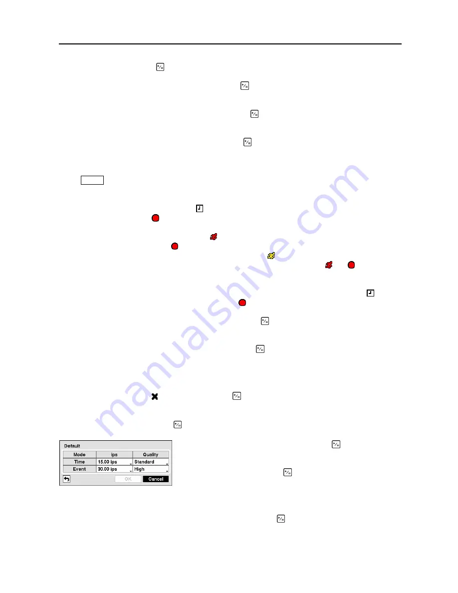
Highlight 

Default… 

and press the   button.  The Default screen appears. 


Figure 51 

 Default setup screen. 

 
You can save your changes by highlighting 

Save 

and pressing the   button.  Selecting 

Cancel

 exits the 

screen without saving the changes. 


Highlighting boxes under 

ips

 and pressing the   button allows you 

to set the images per second for Time and Event recording.  You can 
select from 0.10 to 30.0 images per second.  Highlighting boxes 
under 

Quality

 and pressing the   button allows you to set the 

recorded image quality for Time and Event recording.  You can 
select from:  

Very High

High

Standard

 and 

Basic

.


Summary of Contents for CADV-H-SR08 EH-Series

Page 1: ...EH Series DVRs SR Models CADV H SR16 16 Channel DVR w 160 GB Hard Drive CADV H SR08 8 Channel DVR w 160 GB Hard Drive A Napco Security Group Company 355 Bayview Ave Amityville NY 11701 P 631 842 9400...

Page 2: ......

Page 3: ......

Page 4: ...IDE REASONABLE PROTECTION AGAINST HARMFUL INTERFERENCE WHEN THE EQUIPMENT IS OPERATED IN A COMMERCIAL ENVIRONMENT THIS EQUIPMENT GENERATES USES AND CAN RADIATE RADIO FREQUENCY ENERGY AND IF NOT INSTAL...

Page 5: ...ipment C If the equipment has been exposed to rain or water D If the equipment does not operate normally by following the operating instructions adjust only those controls that are covered by the oper...

Page 6: ...tory Reset Switch 6 Power Cord Connector 6 Chapter 3 Configuration 7 Front Panel Controls 7 POWER LED 7 HDD LED 7 Alarm Out LED 7 NETWORK LED 8 Clip Copy LED 8 Camera Buttons 1 to 16 8 PLAY PAUSE Butt...

Page 7: ...Screen 36 Pre Event Screen 38 Event Settings 38 Alarm In Screen 39 Motion Detection Screen 41 Video Loss Screen 44 Text In Screen 46 System Event Screen 50 Event Status Screen 53 Chapter 4 Operation 5...

Page 8: ...the USB IDE hard disk drive in Windows 98 73 Appendix B Reviewing Video Clips 74 Appendix C WebGuard 76 Web Monitoring Mode 77 Web Search Mode 78 Appendix D Time Overlap 80 Appendix E Troubleshooting...

Page 9: ...een 19 Figure 22 Shutdown screen 20 Figure 23 Logout screen 20 Figure 24 Network Menu 21 Figure 25 Network setup screen 21 Figure 26 LAN Manual setup screen 22 Figure 27 Port Numbers setup screen 22 F...

Page 10: ...tings screen 46 Figure 70 Text In Device Settings screen 47 Figure 71 Text In Actions 1 screen 48 Figure 72 Text In Actions 2 screen 49 Figure 73 Health Check screen 50 Figure 74 Check Recording scree...

Page 11: ...User s Manual viii...

Page 12: ...industry standard protocol y Built in CD RW Drive y Self diagnostics with automatic notification including hard disk drive S M A R T protocol Technical Overview In addition to replacing both a time la...

Page 13: ...to upgrade the system or copy video clips to external hard disk CD RW and flash drives NOTE This manual covers the 8 and 16 channel digital video recorders The DVRs are identical except for the numbe...

Page 14: ...install the DVR Refer to the installation manuals for the other items that make up part of your system Figure 2 16 Channel DVR rear panel Video Input Video Loop Through Audio In Out Video Out RS232C P...

Page 15: ...n you have the correct cable when purchasing the modem Network Port Your DVR can record audio from up to two sources Connect the audio sources to Audio In 1 and Audio In 2 as needed using RCA jacks Co...

Page 16: ...ration for configuring alarm output ARI Alarm Reset In An external signal to the Alarm Reset In can be used to reset both the Alarm Out signal and the DVR s internal buzzer Mechanical or electrical sw...

Page 17: ...t panel are lit NOTE When the DVR successfully resets to factory defaults all the LEDs on the front panel flash five times 5 Release the reset switch All of the DVR s settings are now at the original...

Page 18: ...ctors The front panel looks and operates much like a VCR combined with a multiplexer Many of the buttons have multiple functions The following describes each button and control Take a few minutes to r...

Page 19: ...ghted item or completes an entry that you have made during system setup Arrow Buttons These buttons are used to navigate through menus and GUI You can also use them to change numbers by highlighting a...

Page 20: ...paused Pressing the Play Pause button plays back video at regular speed The screen displays when the DVR is in the Pause mode and the screen displays when the DVR is playing back video ZOOM PTZ Butto...

Page 21: ...amera audio remote control record mode network and password Your DVR can be set up using various screens and dialog boxes Throughout the screens you will see Highlighting the and pressing the Play Pau...

Page 22: ...Virtual Keyboard Use the arrow keys to highlight the character you want in the name or title and press the button That character appears in the title bar and the cursor moves to the next position Pres...

Page 23: ...and press the button The box beside Version displays the software version of the DVR To upgrade the software connect a USB device containing the upgrade package file to the DVR Highlight Upgrade and p...

Page 24: ...it the screen If you do not wish to save the changes highlight Cancel and press the button to exit the screen Figure 9 Setup Import screen Select the desired setup file and press the Import button to...

Page 25: ...t the first box beside Time and press the button The individual sections of the time will highlight Use the Up and Down arrow buttons to change the number Use the Left and Right arrow buttons to move...

Page 26: ...iday has passed Highlighting the Time Sync tab causes the Time Sync screen to display You can set up time synchronization between the DVR and standard time servers that are available in most time zone...

Page 27: ...en The information in the Type column describes the storage device The capacity of the storage device is displayed in the Capacity column The Format column displays whether the device is used for reco...

Page 28: ...mal y Bad Data cannot be written on or read from the storage device y N A Storage conditions are normal however the S M A R T monitoring is not working or supported NOTE When the storage condition is...

Page 29: ...oup and press the button Highlighting a Group Name and pressing the button allows you to change the authority levels assigned to the group CAUTION Write down the new password and save it in a secure p...

Page 30: ...check the remote system status as a batch process on a PC running RAS y Record Setup The user can establish all Record settings on a local system or a PC running RAS y Search The user can access the S...

Page 31: ...ing the button Selecting Cancel exits the screen without saving the changes Shutdown Screen Highlight Shutdown in the System menu and press the button The Shutdown screen displays asking you to confir...

Page 32: ...he Transfer Speed from 50Kbps to 100Mbps Highlight the second box beside Transfer Speed You can select the unit of measure for the transfer speed between bps and ips Press the button to set the transf...

Page 33: ...the numbers by highlighting them and using the Up and Down arrow buttons to increase or decrease the number The factory default LAN settings are IP Address 192 168 1 129 Gateway 192 168 1 254 Subnet...

Page 34: ...or WebGuard CAUTION When changing the port settings you must change the port settings on the PC running RAS or WebGuard as well Refer to the RAS manual for details Selecting DHCP from the Type and hig...

Page 35: ...m Setup Highlight the Modem tab and the Modem screen displays Figure 30 Modem setup screen NOTE If the RS232 port is in use for remote control networking cannot be configured for a modem Highlight Ena...

Page 36: ...to enter the IP address or domain name of the DVRNS server NOTE You will need to get the IP Address or domain name of the DVRNS Server from your network administrator NOTE You can use the domain name...

Page 37: ...le DVRNS servers Please contact your network administrator when you want to register the DVR to another DVRNS server Notification Setup The DVR can be set up to send an email or to contact a computer...

Page 38: ...ht the Callback tab and the Callback screen displays Figure 34 Notification Callback setup screen Highlight LAN and press the button to toggle between On and Off When LAN is turned On you can change t...

Page 39: ...ng Devices You can configure the video audio alarm display and remote control devices connected to the DVR Figure 35 Devices Menu Camera Setup Screen Highlight Camera in the Devices menu and press the...

Page 40: ...assign IDs to each camera by highlighting the box under the ID heading and pressing the button Change the number by highlighting it and using the Up and Down arrow buttons to increase and decrease th...

Page 41: ...ghlight Enable Audio Out and press the button This toggles between enabling and disabling audio out NOTE The DVR will NOT record audio when the recording speed is set to less than 1 ips You can save y...

Page 42: ...ng the button allows you to edit the information in those boxes The Day box allows you to select the days that the alarm schedule will be active The choices are Sun Mon Tue Wed Thu Fri Sat M F Hol and...

Page 43: ...de of the 8 channel DVR y Free Space The icon displays when the DVR is in the Recycle mode and the percentage of available storage space displays when the DVR is not in the Recycle mode y Date Time Th...

Page 44: ...quence through the different screen layouts pages so that all the cameras will be displayed You can also set up the DVR to display one camera or a group of cameras all the time while cycling through t...

Page 45: ...aving the changes Remote Control Screen Highlight Remote Control in the Devices menu and press the button The Remote Control setup screen allows you to select a port and make correct settings for a re...

Page 46: ...n the Record menu and press the button The Record setup screen appears Figure 49 Record setup screen Highlighting Recycle and pressing the button toggles between On and Off In the Recycle mode the DVR...

Page 47: ...he images per second for Panic recording You can select from 0 10 to 30 0 images per second Highlighting the Panic Recording Quality and pressing the button allows you to set the recorded image qualit...

Page 48: ...ys when there is no event and the DVR is not recording When the DVR is in the Pre Event mode the red and display when any event occurs and the DVR starts recoding When the DVR is in the Time Event mod...

Page 49: ...he image speed can be set from 0 10 to 30 00 ips 25 00 ips PAL and image quality can be selectable from Very High High Standard and Basic You can set the amount of time to record prior to the event by...

Page 50: ...eyboard appears allowing you to enter a title name Each input can be set as NO normally open or NC normally closed You can set up the DVR to start panic recording whenever it senses an input on one of...

Page 51: ...the Alarm Out action the alarm output and beep you select should be set to the Event mode in the Alarm Out setup screen Schedule tab Highlight the desired box under the Notify heading and press the b...

Page 52: ...reen Your DVR has built in video motion detection Video motion detection can be turned On or Off for each camera Highlighting the box under the Sensitivity heading and pressing the button allows you t...

Page 53: ...the button A list of intervals ranging from 1 to 10 seconds or Never appears The DVR will not log and notify motion events occurred during the preset interval range NOTE The record action for motion...

Page 54: ...he Event or Time Event recording mode in the Record Schedule setup screen Highlight the box under the Alarm Out heading and press the button A list of Alarm Outputs appears You can associate Alarm Out...

Page 55: ...with a camera The DVR will display the associated camera on the SPOT monitor whenever it detects motions on the selected camera You can save your Motion Detection changes by highlighting Save and pres...

Page 56: ...the Record Schedule setup screen Highlight the box under the Alarm Out heading and press the button A list of Alarm Outputs appears You can associate Alarm Outs with that camera as you wish When the D...

Page 57: ...an be associated with a camera The DVR will display the associated camera on the SPOT monitor whenever it detects video loss on the selected camera You can save your Video Loss changes by highlighting...

Page 58: ...side Text In Product and press the button Select your device from the list NOTE The following description is for a Generic Text Device The screen changes for different types of text input devices and...

Page 59: ...ive If the device distinguishes between upper and lower case letters make certain the Case Sensitive box is turned On Highlight the Actions 1 and Actions 2 tabs and the Text In Actions 1 and Actions 2...

Page 60: ...ation setup screen and the DVR should be registered in the RAS Remote Administration System Figure 72 Text In Actions 2 screen Highlight the desired box under the PTZ heading and press the button A li...

Page 61: ...box beside Check Recording and press the button The Check Recording screen appears Highlighting the box under the Interval heading beside each alarm in and pressing the button allows you to change the...

Page 62: ...A R T Setup screen Highlight Enable and press the button to toggle between On and Off NOTE If Enable is turned Off you will not be able to make changes to any of the boxes Highlight the box beside Ch...

Page 63: ...n associate as many Alarm Outs with the Event as you wish If the DVR detects that event it triggers output signals on all the associated Alarm Out connectors You can also have the DVR s internal buzze...

Page 64: ...setup screen on the Event menu Check Alarm In and Check Recording will be highlighted when each event is detected based on the settings you made in the System Event setup screen on the Event menu Pani...

Page 65: ...User s Manual 54...

Page 66: ...he DISPLAY button cycles the DVR through the different display formats The DVR can be set to display full screen video for a preset dwell time when an Event occurs Video from the lowest camera number...

Page 67: ...s and monitors are correctly installed and adjusted prior to making any image adjustments using the DVR s controls If a user who has Color Control authority logs into the system the user can adjust th...

Page 68: ...d status icons will be displayed on the monitor If a camera is set up as Covert 2 in the Camera setup screen Settings tab that camera appears to be Off unless a user with Covert Camera View authority...

Page 69: ...Press the camera button 1 to zoom in and press the button 2 to zoom out You can use the button 3 and button 4 to focus the image You can establish preset positions for PTZ cameras Press the camera bu...

Page 70: ...ra image switches that camera to full screen Clicking the mouse button again returns to the previous multi view format When in one of the multi view formats scrolling the mouse wheel up and down opera...

Page 71: ...in stops panic recording If you set the Panic Recording Duration in the Record Screen panic recording will stop automatically according to the preset duration as long as the PANIC button is not presse...

Page 72: ...o seconds or longer enters the cameo mode The yellow outline surrounding the video indicates the active cameo and pressing the arrow buttons moves the active cameo Pressing the desired camera button i...

Page 73: ...de displays the Search Menu Figure 86 Search menu y Go to the First Displays the first recorded image y Go to the Last Displays the last recorded image y Go to the Date Time Searches by date and time...

Page 74: ...ith white numbers You can highlight the days with recorded video by using the arrow buttons Once you have highlighted a day press the Play Pause button to select it A time bar displays at the bottom o...

Page 75: ...ow buttons to highlight the event for which you would like to see video The Event Log Search screen can also be accessed by pressing the ALARM button unless there is an alarm There is no determined us...

Page 76: ...time When set to On you will be asked to select one of the overlapping start and stop time When set to Off the DVR will display search results from all start times to all stop times Highlight the box...

Page 77: ...lays this list Use the arrow buttons to highlight the event for which you would like to see video Pressing the Play Pause button will extract the video associated with the Text Input and display the f...

Page 78: ...Input Device from the list NOTE The following description is for a Generic Text Device The screen changes for different types of text input devices and there will be different parameter boxes for you...

Page 79: ...Pressing the button will start playing the event video segment Pressing PLAYBACK returns to live monitoring You can also narrow your event search by selecting the Option button and setting up the new...

Page 80: ...lected Once you set your desired search conditions highlight Search and press the button to display the search results in the Motion Search screen Selecting Cancel exits the screen without saving the...

Page 81: ...can select the storage device on which you would like to record the video clip You can choose from Internal CD RW Internal DVD RW USB Storage and USB CD RW CAUTION The USB device for clip copy must be...

Page 82: ...lip copy is limited to 2GB You can use other functions on the DVR while video is being backed up To do this highlight the Close button and press the button You can return to the Clip Copy screen at an...

Page 83: ...User s Manual 72...

Page 84: ...drive in Windows 98 NOTE Preparing a USB IDE hard disk drive under Windows ME is almost identical to Windows 98 1 Connect the USB IDE hard disk drive to your computer using the USB Cable 2 Turn on yo...

Page 85: ...proper operation Figure 96 ClipPlayer screen The ClipPlayer Screen displays the clip images NOTE Proper image display depends on the display settings of your PC If you are experiencing display problem...

Page 86: ...eo Format allows you to find appropriate display environments that can be varied depending on the type of graphics card installed in your PC Use Video Format option when you are experiencing improper...

Page 87: ...trator permissions Click the right mouse button on the Internet Explorer icon and select the Run as administrator option from the context menu Otherwise some functions of WebGuard might be limited to...

Page 88: ...The DVR information window displays the time information of the remote DVR and login information of WebGuard Click the screen format to select the desired display mode When changing the screen format...

Page 89: ...ng the Camera Title blank causes the camera name set up on the remote site to display Web Search Mode WebSearch is a remote web search program that allows you to search recorded video on the remote DV...

Page 90: ...ou want to search Clicking a specific time displays the image recorded at that time on the screen Selecting the allows you to display an image from a specific time Click the to enter the event search...

Page 91: ...reams by selecting a specific time or time range If you want to search recorded video at four o clock during the overlapping time range using a search menu such as Go to the Date Time select the segme...

Page 92: ...lens settings Live Video Very Bright If a cable is attached to the Loop connector make certain it is connected to a properly terminated device DVR has stopped recording If hard disk drive is full you...

Page 93: ...nector Pin Outs I O Connector Pin Outs AI 1 to 16 Alarm Inputs 1 to 16 GND Chassis Ground 5 connectors AO 1 to 2 Alarm Outputs 1 to 2 ARI Alarm Reset In RS485 Connector Pin Outs Master Unit Slave Unit...

Page 94: ...Digital Video Recorder 83 Appendix G Map of Screens...

Page 95: ...Off Power Failure Panic On Time Change Panic Off Time Zone Change Clear All Data Time Sync Clear Disk Time Sync Fail Format Disk Disk Bad Disk Full Login Auto Deletion Logout Search Begin Setup Begin...

Page 96: ...failed 8 Opening disk failed 104 Rebooting failed 9 Formatting disk failed 105 Invalid package 10 Database has been changed 106 ODD firmware upgrade failed 11 Appending failed 300 Remote connection fa...

Page 97: ...et RJ 45 RS232C for external modem Audio Input RCA Input 2 Line In Audio Output RCA Output 1 Line Out Text Input POS Interface ATM Interface CONNECTORS Video Input Composite 8 or 16 BNC Video Loop Com...

Page 98: ...t 25 6 lbs 11 6kg Shipping Dimensions W x H x D 21 3 x 11 4 x 23 2 540mm x 290mm x 590mm Operating Temperature 41 F to 104 F 5 C to 40 C Operating Humidity 0 to 90 Power 100 240 VAC 4 2 A 60 50Hz Powe...

Page 99: ...or human health from uncontrolled waste disposal please separate this from other types of wastes and recycle it responsibly to promote the sustainable reuse of material resources Household users shou...

Reviews: