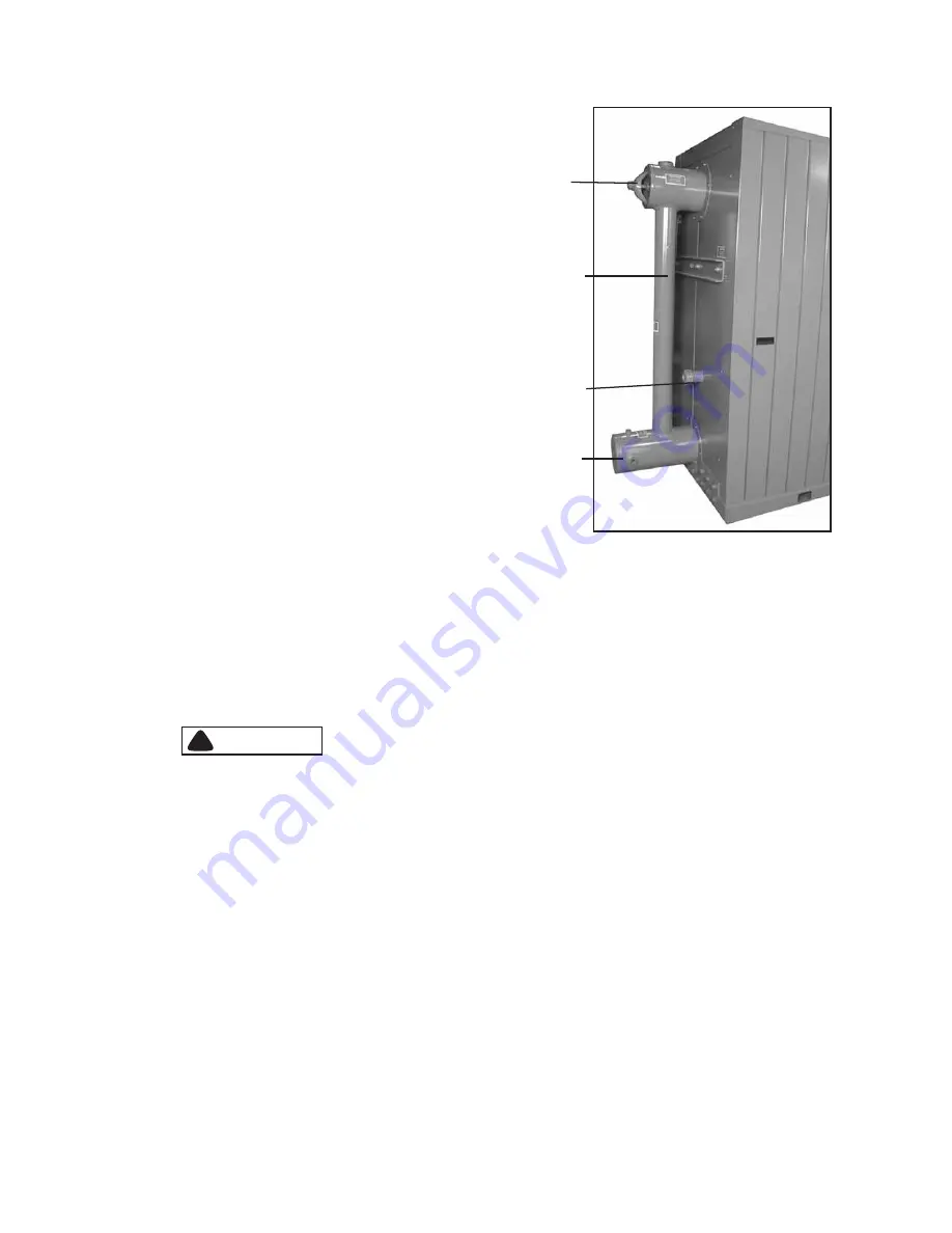
UPPER
DOWNCOMER
SYSTEM INLET
SIGHT PORT
Figure 3-5: Rear Panel (Hot Water Boiler
HAND HOLE
Chapter 3
General Description
3-8
750-177
Boilout Procedure
1. Prepare the boiler for firing by taking the standard
precautions. Check for any situations that might present a
hazard.
2. Remove upper and lower drum handhole covers and inspect
all internal waterside surfaces. Remove debris and wash all
internal surfaces, including tubes. It may be necessary to
use a high pressure hose or a wash out lance to flush out
inaccessible areas. Reinstall the lower drum handhole cover.
(Use standard service gaskets during the boilout procedure.)
3. The relief valve(s) must be removed before adding the
boilout solution so that neither the solution nor the
contaminants that it may carry can come in contact with the
valve(s). Use care in removing, handling, and reinstalling
these valves.
Note: For relief valve installation information, refer to
Chapter 8, Section E. “Controls.”
4. Replace the regular gauge glass with a temporary gauge
glass that can be discarded after the cleaning (steam
boilers).
5. An overflow pipe should be connected to one of the top
boiler openings and routed to a safe point of discharge. A
relief valve tapping is usually used for this purpose. The overflow connection to the boiler should incorporate a tee
fitting for adding cleaning solution to the boiler.
6. Fill the unit with clean water to a point just below the access port in the upper drum. It is important that the water
used for the filling process is at a temperature of 70°F or above.
7. Add the boilout solution using a chemical pump.
!
DANGER
WARNING
The chemicals used in this procedure are corrosive to eyes and skin. Always refer to the Material
Safety Data Sheet to ensure that the proper safety equipment and precautions are present. Failure
to heed this warning could result in serious personal injury or death.
8. Reinstall the upper handhole cover.
9. Continue to fill the boiler until it is full (indicated by flow from the overflow connection).
10. Recheck the burner, gauge glass, pressure gauge, feedwater supply and the position of all valves. Make sure that all
water feeding and level indicating apparatus are in proper working condition.
11. Fire the boiler intermittently at the burners lowest fire rate until the water reaches the boiling point. The water should
be held at this temperature for at least five hours.
Note: Do not produce pressure in the boiler.
12. Throughout the entire process, each blow-down point or valve should be blown at least once every two hours. The
total amount of water blown from all points each time should be approximately one-half gauge glass, this amount
being equally divided among the various manual blowdown points and continuous blowdown system. Blow the
surface and/or continuous blow-down points first, followed by the other blowdown points lower on the boiler. After
each blowdown cycle, the water level should be brought back to full. If the total alkalinity in the cleaning solution
falls to a level below 3000 ppm, it may be necessary to add additional solution, using a chemical pump.
Summary of Contents for FLX 1000
Page 12: ...Chapter 1 General Description 1 6 750 177...
Page 68: ...Chapter 2 Profire V Burner 2 56 750 177...
Page 90: ...Chapter 4 Sequence of Operation 4 10 750 177...
Page 104: ...Chapter 5 Adjustment Procedures 5 14 750 177...
Page 110: ...Chapter 6 Troubleshooting 6 6 750 177...
Page 122: ...8 2 750 177 Figure 8 1 Typical Hot Water Flextube Casing...
Page 124: ...8 4 750 177 Figure 8 2 Typical Low Pressure Steam Flextube Casing...
Page 126: ...8 6 750 177 Figure 8 3 Typical High Pressure Steam Flextube Casing...
Page 128: ...Parts Chapter 8 8 8 750 177 Steam Pressure Controls...
Page 129: ...Chapter 8 Parts 750 177 8 9 Water Level Controls...
Page 130: ...Parts Chapter 8 8 10 750 177 Water Level Controls continued...
Page 131: ...Chapter 8 Parts 750 177 8 11 Water Column Main and Aux 15 Steam...
Page 132: ...Parts Chapter 8 8 12 750 177 Water Column Main and Aux 150 Steam...
Page 133: ...Chapter 8 Parts 750 177 8 13 Safety Valves...
Page 134: ...Parts Chapter 8 8 14 750 177...
Page 135: ......
Page 136: ...e mail info cleaverbrooks com Web Address http www cleaverbrooks com...


