Profire V Burner
Chapter 2
750-177
2-9
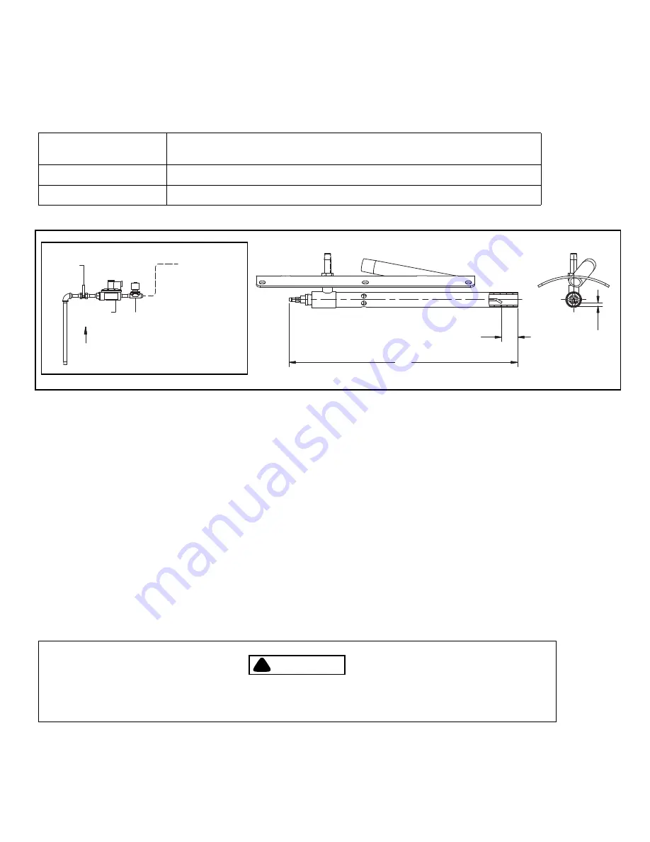
PILOT GAS TRAIN COMPONENTS
Models VL 60-168 as well as all VG and VLG models are supplied with a gas pilot system. Oil only models VL 13-55
are supplied with direct spark ignition.
Gas Pilot Valve
A solenoid valve that opens during the ignition period to admit fuel to the pilot. It closes
after main flame is established.
Gas Pressure Regulator
Reduces gas pressure to that required by the pilot.
Gas Pilot Shutoff Cock
For manually closing the pilot gas supply.
14.18
1.00
WITHIN
ELECTRODE END
"
TUBE END
TIP TO TUBE
GAP OF .16"
GAS PILOT
TO GAS PILOT
REGULATOR
PILOT
VALVE
PILOT
SHUTOFF
COCK
GAS
FLOW
PILOT TRAIN
Figure 2-7: Pilot train / Pilot assembly
E. Installation
DRAFT CONDITIONS
A boiler or other heating vessel fired with a V series burner does not depend on chimney draft for proper combustion
air. Combustion air is supplied by the burner forced draft blower providing adequate air for any normal combustion
condition. Since draft control is essential to maximum efficiency, a draft regulator maybe required when the vessel is
connected to a tall stack or where wind conditions may cause erratic draft.Excessive furnace draft contributes to
inefficient burner operation. Sealed boilers may be operated under positive firebox pressure within the capability of the
burner.
COMBUSTION AIR SUPPLY
The space in which the burner operates must be supplied with adequate fresh air for combustion and ventilation
purposes. Fresh air supply must meet or exceed all code requirements. Consult with insurance carrier and/or local
authorities for specific regulations.
!
DANGER
CAUTION
!
DANGER
WARNING
THE BOILER ROOM PRESSURE MUST BE AT LEAST EQUAL TO THE OUTDOOR ATMOSHERIC PRESSURE. WHERE FAN
VENTILATION IS USED, AIR MUST BE FORCED INTO THE BOILER ROOM. NEVER EXHAUST AIR FROM THE BOILER
ROOM. ADJOINING AREAS HAVING EXHAUST FANS MUST BE POSITIVELY ISOLATED FROM THE BOILER ROOM.
Summary of Contents for FLX 1000
Page 12: ...Chapter 1 General Description 1 6 750 177...
Page 68: ...Chapter 2 Profire V Burner 2 56 750 177...
Page 90: ...Chapter 4 Sequence of Operation 4 10 750 177...
Page 104: ...Chapter 5 Adjustment Procedures 5 14 750 177...
Page 110: ...Chapter 6 Troubleshooting 6 6 750 177...
Page 122: ...8 2 750 177 Figure 8 1 Typical Hot Water Flextube Casing...
Page 124: ...8 4 750 177 Figure 8 2 Typical Low Pressure Steam Flextube Casing...
Page 126: ...8 6 750 177 Figure 8 3 Typical High Pressure Steam Flextube Casing...
Page 128: ...Parts Chapter 8 8 8 750 177 Steam Pressure Controls...
Page 129: ...Chapter 8 Parts 750 177 8 9 Water Level Controls...
Page 130: ...Parts Chapter 8 8 10 750 177 Water Level Controls continued...
Page 131: ...Chapter 8 Parts 750 177 8 11 Water Column Main and Aux 15 Steam...
Page 132: ...Parts Chapter 8 8 12 750 177 Water Column Main and Aux 150 Steam...
Page 133: ...Chapter 8 Parts 750 177 8 13 Safety Valves...
Page 134: ...Parts Chapter 8 8 14 750 177...
Page 135: ......
Page 136: ...e mail info cleaverbrooks com Web Address http www cleaverbrooks com...


