Sample Configurations for the Cisco VC 220 Network Camera
Configuring the GPIO Ports
VC 220 Dome WDR Day/Night PoE Network Camera Administration Guide
96
8
Configuring the GPIO Ports
The following instructions help you configure the general input and output (GPIO)
on the Cisco VC220 camera. In general, you will need to:
•
Make the GPIO connections and test the external device connections. See
General Purpose Input and Output Terminal Block, page 16
for
connection diagrams and further information.
•
Setup an event.
Consider the following example:
STEP 1
Make and test the output GPIO connection. For this example, we are using an
alarm as an output device.
a. Connect the output device (alarm) to pin 1 and pin 2.
b. Go to the
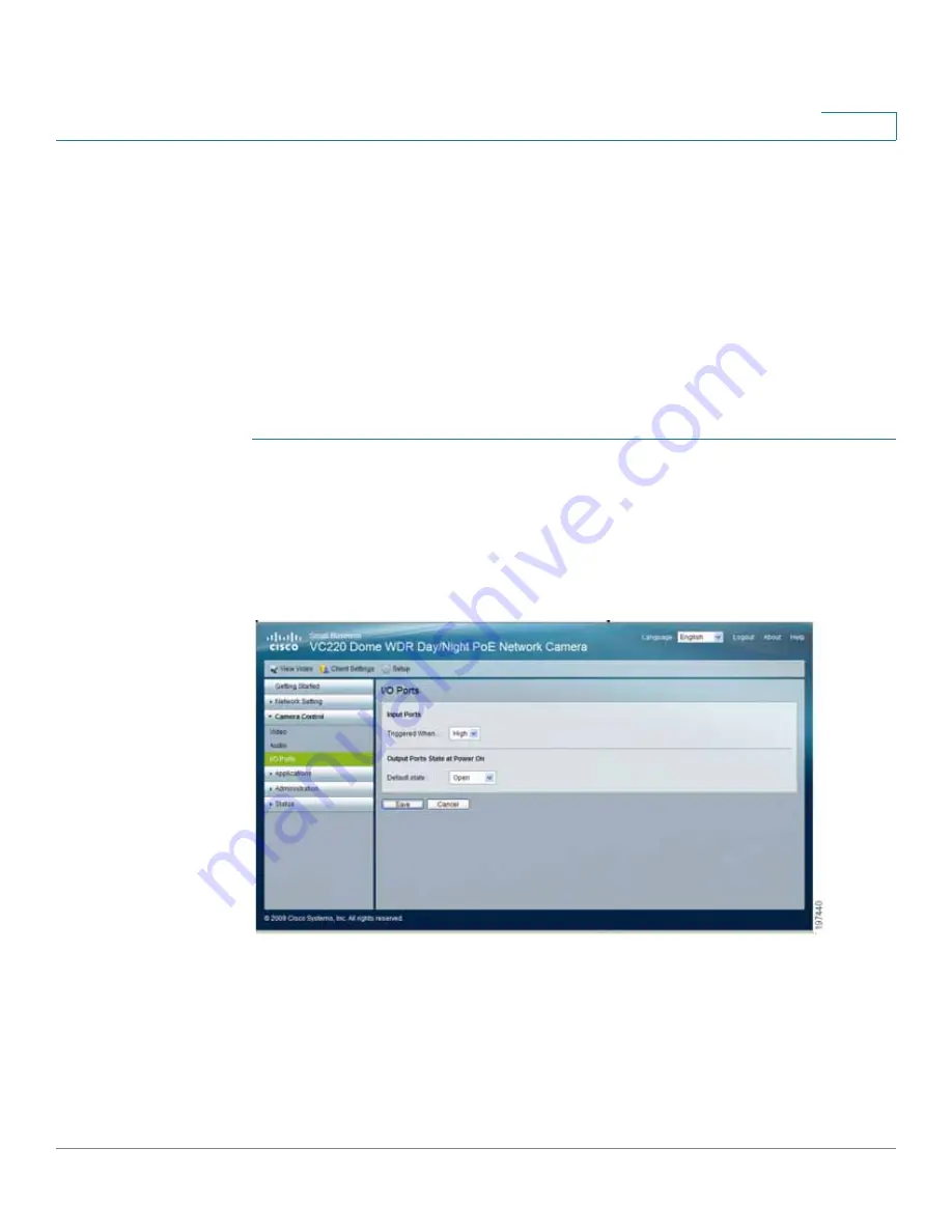
Camera Control > I/O Port
page to select the proper
Default State
for the output port.
c. Go to the
View Video
page
d. Click the
On
button on the
View Video
page. The alarm should turn on.
e. Click the
Off
button on the
View Video
page. The alarm should turn off.
f.
Go to the
Status> System Summary
page.
I/O Port Status
should show the
output as
Triggered
when the alarm is on and
Normal
when the alarm is off.


