14.0 A
PPENDIX
: GPIO
R599790 - FORCE Series User Manual
91
14.0A
PPENDIX
: GPIO
This section explains how to use a GPIO link from the projector to external equipment, such as devices for 3D
synchronizing.
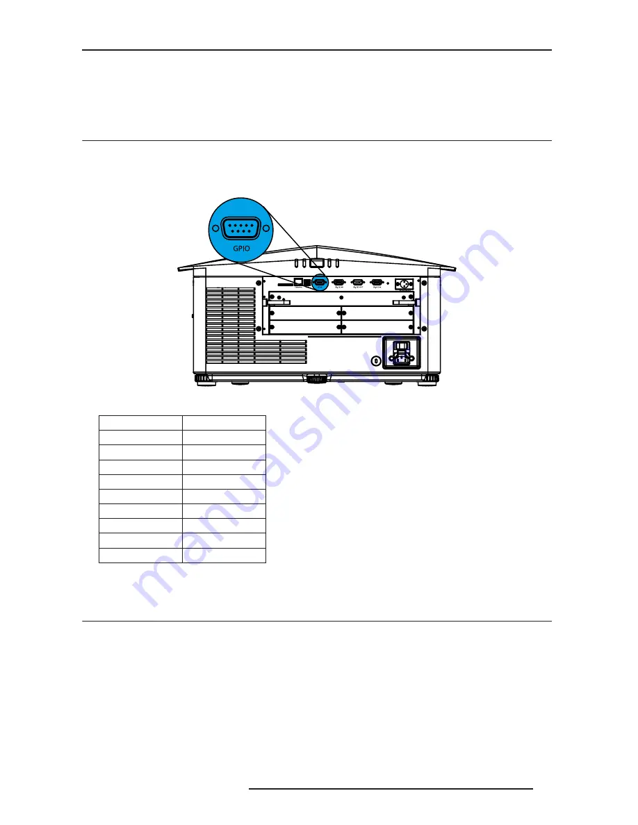
14.1 GPIO Port
The GPIO connector located on the input panel provides a flexible method of interfacing a wide range of external
I/O devices to the projector. There are 7 GIO pins available on the 9pin D-Sub GPIO connector, which are
configurable via RS-232 commands or Web interface. See Figure B-1 -
GPIO Connector. The other two pins are reserved for ground and power - see table below for pin identification.
GPIO Connector
GPIO PINS
The serial cable required for connecting the external device to the projector’s GPIO connector, must be compatible
with the external device.
14.2 Configuring the GPIO
The GPIO connector can be configured to automate any number of events using the serial command code GIO.
Each Pin is defined as either an input or output depending on the desired outcome. Configure the pin as an input if
you want the projector to respond to something the device does and as an output if you want the external device to
respond to an action taken by the projector. For example, configure the pin as an output if you want the lighting in a
room to automatically dim when the projector is turned on.
By using the GIO command, you can also set the state of each output pin as high or low. By default, the state of
each pin is high. The voltage applied to pins in the high state is +3.3V.
A low state (or value of 0) will be read on an input pin if the circuit attached to the pin is open. A high state (orvalue
of 1) will be read on an input pin if the circuit attached to the pin is shorted to ground. This corresponds to a switch
PIN#
Signal
Pin 1
12V (200mA)
Pin 2
GPIO 2
Pin 3
GPIO 4
Pin 4
GPIO 6
Pin 5
Ground
Pin 6
GPIO 1
Pin 7
GPIO 3
Pin 8
GPIO 5
Pin 9
GPIO 7
1 2 3 4 5
6 7 8 9
Summary of Contents for Force one
Page 1: ......
Page 99: ...16 0 APPENDIX DIMENSIONS R599790 FORCE Series User Manual 99...
Page 100: ......