


3.0 GETTING STARTED
R599790 - FORCE Series User Manual
21
below. NOTE: A wireless router can be used to communicate to the projectors via 802.11b/g.
Ethernet Network setup
• Setting the Projector’s IP address, subnet Mask and Gateway
You can refer to “Ethernet Settings”, page 61
Changing the port number#
On some Ethernet networks, firewall restrictions may require that the port number of the projector be changed from
its default of 3002. If so, enter a new port number in the Ethernet Settings menu or include the new port#.
Separating Networks
By default, communications originating from one type of serial controller—RS-232 vs. RS-422 vs. Ethernet— stay
on the corresponding network path. A “Separate” setting indicates this separation for “Network Routing” in the
Communications menu, see “WEB USER INTERFACE”, page 71. If you are using an RS-422 controller, for
example, it will communicate only with the projector to which it is connected unless you change this setting to either
“RS-232 and RS-422 Joined” or “All Joined”.
• Communicating to all Ports
To relay all messages to all ports—RS-232, RS-422, and Ethernet—set the “Network Routing” option in the
Communications menu for each projector to “All Joined”, see “WEB USER INTERFACE”, page 71. This
configuration is useful if you are using a non-RS-232 controller with the RS-232 linking available between these
projectors. For example, you may want to use both an RS-422-compatible controller and an Ethernet connected PC
for working with a network of projectors linked via their RS-232 in/out ports.
To isolate just RS-422 communications, select “RS-232 and Ethernet Joined”.
To isolate just Ethernet communications, select “RS-232 and RS-422 Joined”—only projector #1 will respond via
Ethernet.
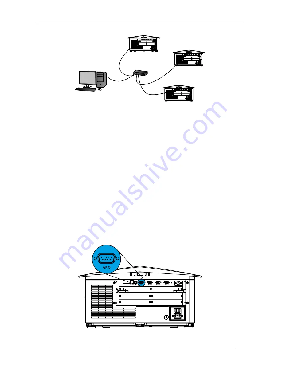
System Integration - GPIO Connector
The GPIO connector on the input panel interface, provides a method of interfacing a wide range of external I/O
devices. Refer to “Appendix: GPIO”, page 91 Connector for complete details on pin configuration and how to
program the GPIO.
Computer
Proj1
Proj2
Proj3
CAT5
CAT5
CAT5
CAT5
HUB
1 2 3 4 5
6 7 8 9
Summary of Contents for Force one
Page 1: ......
Page 99: ...16 0 APPENDIX DIMENSIONS R599790 FORCE Series User Manual 99...
Page 100: ......


