7.0 USING INPUTS AND CHANNELS
44
R599790 - FORCE Series User Manual
first channel with matching characteristics.
Creating a New Channel
To use a new source with the projector, a new channel must be created so that the projector will respond to an input
signal from that source. A new channel can be created automatically, or it can be copied from an existing channel
and then edited as necessary.
When you select a direct input (SLOT 1, SLOT 2, SLOT 3, or SLOT 4), any existing channels in the projector are
searched for matching input and signal parameters – this only occurs if Auto Source is enabled on these channels.
If no match to the incoming input signal is found in currently defined channels, a new channel is temporarily created
based on factory-defined defaults for this type of signal. The channel number assigned is the lowest available
number from 01-99.
NOTES:
1) An automatic channel will be discarded unless one or more of its parameters are changed and will not appear in
the channel list (see below).
2) If 2 channels have the same distinguishing source characteristics except for the reversal of sync connectors (i.e.,
H-sync and Vsync, are switched), they are still defined as distinct channels.
3) You cannot define a new channel without an incoming signal.
Using a Channel
You can normally select a channel at any time by pressing CHANNEL (see below). If you want to hide a channel
from appearing in this list, you must edit the channel refer to Channel Edit. Such a channel can still be selected by
entering its number as shown below.
Using a Channel
NOTES:
1) The current channel is highlighted in the channel list, or, if the current channel is hidden, the first channel in the
list is highlighted.
2) Channels created automatically do not appear in the channel list unless a parameter for the channel has been
changed.
7.2
Channel Setup Menu
All available channels are listed in the Channel Setup menu, which describes how each channel can be accessed
and provides access for editing, copying and deleting channels.
Press MENU from the presentation level to display the Main menu. To display the Channel Setup menu, press 3, or
move the highlight to the Channel Setup option and press ENTER. The Channel Setup menu will appear (see
sample below).
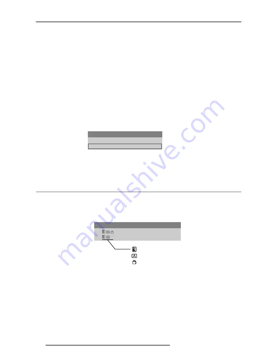
Channel Setup Menu
The channel setup icons list all defined channels. The far left column lists channel numbers defined. The values in
the far right columns indicate horizontal and vertical frequencies or if there is a defined name for a channel, it
appears here. The H & V frequencies will not appear if a name has been defined for the channel; instead the name
is only seen. The H & V frequencies are inserted as, the name when the channel is first created. The vertical
frequency is displayed with the sync polarity. The remaining columns pertain to each signal type; such as, input
number, slot location, a variety of icons indicating access to each channel, and an abbreviated description of each
signal type.
NOTE: Use UP ARROW KEY and DOWN ARROW KEY to see the remaining channels not visible in the initial
display of channels.
Signal Type
The channel list or the Channel Setup menu, identifies signal types abbreviations as defined in the table below.
Main Channel: 01
01. 1,2 iSVid
15.73kHz- i59.94-Hz-
02. 4,1 pDig
33.72kHz+ p29.07-Hz+
To change Channel:
Enter 2-digits channel#
or
Move highlighted and
press ENTER.
Channel Setup
01.
1,2
iSVid
15.73kHz- i59.94-Hz-
02.
4,1
pDig
33.72kHz+ p29.07-Hz+
Appears in Chan. List
Auto-Source
Locked
Summary of Contents for Force one
Page 1: ......
Page 99: ...16 0 APPENDIX DIMENSIONS R599790 FORCE Series User Manual 99...
Page 100: ......