4.0 CONNECTING SOURCES
R599790 - FORCE Series User Manual
25
4.4
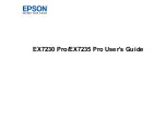
Dual-link DVI Input Board
This card accepts a single DVI signal with or without High-Bandwidth Digital Content Protection (HDCP) video
signal over a DVI-I connector and analog video signals over the DVI-I or 15-pin VGA connector.
The module can simultaneously support a digital signal on the DVI input and an analog signal on the VGA port,
however it does not support 2 analog signals at the same time. There are 4 LEDs on the module faceplate.
NOTE: PWR LED indicates that power is applied and the card is initialized, and the other 3 on the right side of the
corresponding connectors indicate that a valid signal has been detected.
Dual-link DVI input board
4.5
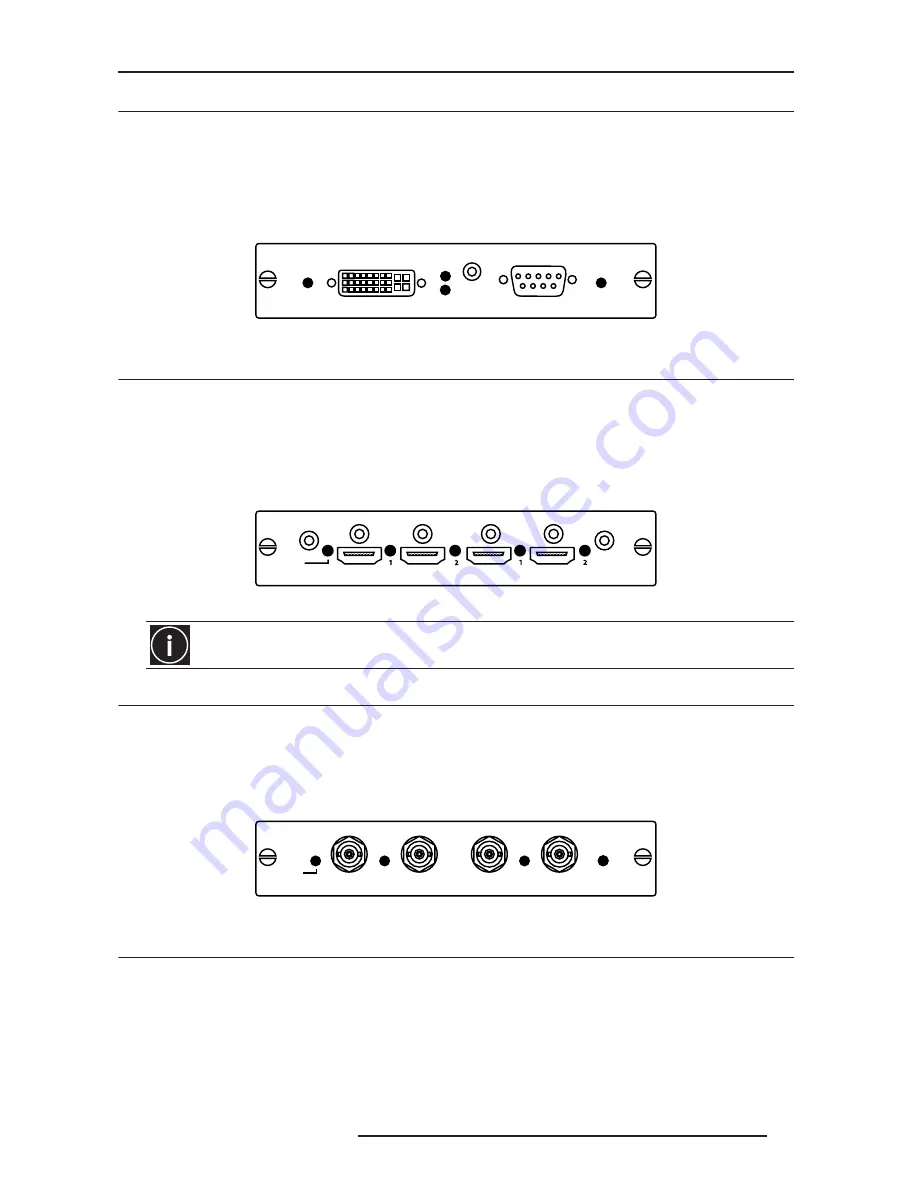
Twin HDMI Input Board
This card accepts one or two HDMI inputs, and can route one or both inputs to the card’s outputs. Any input from
any card can be looped out of this card. The output label ‘1-OUT’ loops out the main image being displayed on the
projector. The output labelled ‘2-OUT’ loops out the image displayed in the picture in picture (PIP). Any input from
any optional input card can be looped out of this card. There are 5 LEDs on the module faceplate. The PWR on the
left side indicates power is applied, and that the card is initialized. The LEDs to the right side of the corresponding
connectors indicate that a valid signal is detected. In the case of the output’s, the LED indicates a signal is currently
being looped out.
Twin HDMI input board
4.6
Dual SD/HD - SDI Input Board
This card accepts both standard-definition (SD) and high-definition (HD) serial-digital-interface (SDI) signals from 1
of 2 standard-definition (SD) or high-definition (HD) SDI sources.
Both single-link HD and dual-link HD signals are accepted. The card has two SD/HD-SDI outputs, each of which is
“loop through” for its respective input.
NOTE: There are 3 LEDs on the module faceplate. PWR indicates power has been applied and the card is
initialized, and the two signal LEDs indicate a valid signal has been detected on the respective input.
Dual SD/HD - SDI input board*
4.7
Standard Video Input Board
This card accepts and decodes standard definition (SD) video. This includes CVBS (composite video), SVideo, and
component sources. This card supports as many as 6 video signals, four of them on BNC connectors and two on 4-
pin mini-DIN connectors. Each mini-DIN connector accepts 1 S-Video signal. The first BNC accepts composite
video (only), while the remaining three BNC’s can be grouped to allow one of the following combinations:
•
3 CVBS sources on 4, 5 & 6
•
1 CVBS source, 1 S-Video source: Luma (Y) connected to 4(Sy) and Chroma (C) connected to 6 (Sc)
•
1 YPbPr source: component signal on 4 (Pr), 5 (Y) & 6 (Pb)
Make sure to use a certified HDMI cable, especially when the distance between the different devices are
longer than 5 meters. If it is the case, the use of a split system or optical fiber cable is highly recommended.
1 - Dual Link DVI-I
PWR
Dual Link DVI Input
Digital
Signal
2 - VGA
Analog
1 - IN
PWR
Twin HDMI Input
2 - OUT
2 - IN
1 - OUT
1 - IN
Signal
PWR
Dual SD/HD - SDI Input
1 - OUT
2 - IN
2 - OUT
Signal
Signal
Summary of Contents for Force one
Page 1: ......
Page 99: ...16 0 APPENDIX DIMENSIONS R599790 FORCE Series User Manual 99...
Page 100: ......