2.0 INSTALLATION GUIDELINES
R599790 - FORCE Series User Manual
9
2.3
Lens Installation
Installing a projection lens
The projection lens, shipped separately from the projector, must be installed prior to setting up the projector.
Remove the lens plug from the lens opening in the projector before installing the lens.
Retain the lens plug for projector transportation to protect the projector’s optical
components from dust and debris.
• Steps
1) Remove the rear lens cap from the lens. Keep the front lens cap on the lens to protect it during installation.
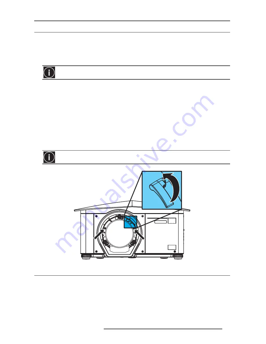
2) Rotate the lens clamp to the OPEN position, see Figure 2-1 Lens Installation.
3) Remove and retain the 2 security screws from the lens mount, see figure below.
4) Align the lens interface plate with the lens mount. Align the lens electrical connector with the mating connector
on the lens mount. Fully insert the assembly straight into the lens mount opening without turning. Press using your
hand. NOTE: When installing the lens, ensure that the lens IS NOT inserted at an angle. as this can cause
damage.
5) While holding the lens flat against the lens mount, rotate the lens clamp clockwise to lock the lens assembly in
place.
6) For added stability such as motion applications, fasten the security screws, provided with the lens mount, using
the tool provided. Recommended for heaviest lenses such as 0.67:1 and 1.1:1.
7) Remove the front lens cap.
Security screw position and lens clamp
2.4
Connecting the Line Cord
Use the line cord provided with the projector, or ensure you are using a line cord, power plug and socket that meet
the appropriate rating standards.
The lens seals the projector, preventing contaminants from entering the interior of the projector. Never
operate this unit without a lens.
The use of 2 lens security screws is required if the projector is hoisted or installed in an overhead position.
Security screw
Lens clamp: rotate
Security screw
anti-clockwise to
OPEN the clamp.
Rotate clockwise
to CLOSE it.
Summary of Contents for Force one
Page 1: ......
Page 99: ...16 0 APPENDIX DIMENSIONS R599790 FORCE Series User Manual 99...
Page 100: ......