background image

Operation 


3-40


Roadster & Mirage S+/HD User Manual 


020-100002-04 Rev. 1 (12-2008)


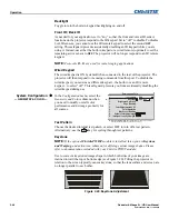
menu. This checkbox must be set by the user for all new 3D sources, and cleared for 
all new non-3D sources (default setting is checked).  Once set, this value will be 
maintained for that source for all future uses. This option is also available under the


Simulation 3D

 menu in Mirage HD projectors only. 

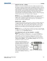
FLOATING INPUTS - 

This allows the signals connected to inputs 1, 3, and 4 to have 

floating ground references relative to the projector. Floating the inputs can remove 
hum bars in the image if the installation has conflicting grounds. However, floating 
the inputs can also introduce hum bars when the signal ground is the only connecting 
ground. Select the setting that produces the best image. 


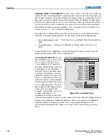
Use the 

Configuration

 menu to 

define general operating 
parameters and communications 
with other projectors and 
equipment, and to access other 
advanced processing and image 
adjustments affecting overall 
performance. In addition, the 

Configuration

 menu provides 

access to diagnostics, calibration 
tools and the 

Service

 submenu 

(password-protected). 

Keep in mind that settings in the 

Configuration

 menu (and its submenus) are typically “global” settings applied 

regardless of the type of source being used. This characteristic is identified with the 

 (globe) icon alongside the option. 

NOTE:

 The 

Configuration

 menu is recommended for experienced users/technicians 

only. 

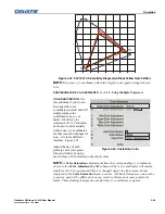
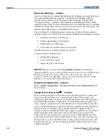
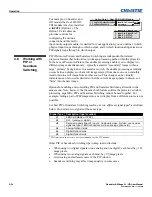
The first six options in the 

Configuration

 menu are explained below: 

Language 

Choose from available languages to use in the projector’s menus. The change will 
take effect immediately. 

Image Orientation 

Set the orientation of the image according to the orientation of your projector. If the 
setting is incorrect, projected images will be reversed and/or upside down. 

Reserved - 

No function.


Auto Power-up 

Enter a checkmark to enable the projector to automatically power up after losing 
power due to a power failure or due to unplugging the projector during operation. 
Note that unsaved display adjustments may be lost. 

Image Orientation

Auto Power Up

Set Date And Time

Menu Preferences

Communications

Geometry and Color

Diagnostics and Calibration

Service

Option 1 Card: Dual SD/HD-SDI

Language

Reserved

Option Card 2 Empty

1.

2.

3.

4.

5.

6.

7.

8.

9.

0.

English

Front

Configuration


3.7 Adjusting 

System 
Parameters and 
Advanced 

Controls 

 System 

Configuration 


— GENERAL —


Summary of Contents for Mirage HD12

Page 1: ...Roadster Mirage S HD U S E R M A N U A L 020 100002 04 ...

Page 2: ......

Page 3: ...Definition Panel Driver 高清晰度驱动 板 X O O O O O Dual SD HD SDI DHDM module 双信号 SD HD SDI 模块 X O O O O O Lamp Contact PCB 灯连接板 X O O O O O LCD status display PCB 状态显示板 X O O O O O Blowers Fans 吹风机 风扇 O O O O O O Sensor 传感器 O O O O O O Illumination optics system 照明光学系统 X O X O O O Projection Lens 投影镜头 X O X O O O Auxiliary optics 辅助光学器件 X O X O O O Mechanical enclosure 机械附件 X O O O O O Software CD 软件光盘...

Page 4: ......

Page 5: ...9 3 1 Overview 3 1 3 2 Projector Basics 3 1 3 3 Using the Keypads 3 4 3 4 Navigating the Menus 3 12 3 5 Using Inputs and Channels 3 16 3 6 Adjusting the Image 3 21 3 7 Adjusting System Parameters and Advanced Controls 3 41 3 8 Working with PIP or Seamless Switching 3 56 3 9 Working with the Lamp 3 59 3 10 Status Menu 3 63 3 11 Using Multiple Projectors 3 63 3 12 Remote Control of the Projector 3 7...

Page 6: ... Rev 1 12 2008 A Glossary A 1 B Remote Keypad B 1 C Serial Communication Cables C 1 D Throw Distance D 1 E System Integration E 1 F Optional Input Modules F 1 NOTE Due to continuing research all information in this manual is subject to change without notice Appendices ...

Page 7: ...A quick change lamp module no tool lens replacement and intuitive user interface means the ultimate in versatility and ease of use These projectors provide brilliant images with 1400 x 1050 SXGA or 1920 x 1080 HD clarity and perfect color saturation in a wide variety of applications The Roadster and Mirage Series each have features for your distinct needs The stereoscopic Mirage projectors provide...

Page 8: ...000 Roadster HD18K or Mirage HD18 18000 Roadster S 20K 20000 Contrast Ratio ANSI lumens 450 1 ANSI 1600 2000 1 Full Field LiteLOC for automatic constant brightness control Quick change bubble style lamp module Inputs There are two different types of Input face plates configurations model dependant See Figure 1 1 1 2 These configurations may include the following inputs One analog RGBHV YPbPr input...

Page 9: ...RS232 RS422 and GPIO control ports Easy view LED for error codes and LCD for status and error messages Voltmeter for monitoring AC The projectors accept data graphics and video input signals for projection on to front or rear flat screens High brightness light is generated by an internal Bubble lamp and then modulated by three Digital Micromirror Device DMD panels that provide digitized red green ...

Page 10: ...In many cases any necessary servicing can be performed on site If you have purchased the projector fill out the Purchase Record below and keep with your records In addition complete the Product Registration at the Christie website this will ensure that you receive all future product communications promptly Purchase Record Dealer Dealer Phone Number Projector Serial Number Purchase Date Installatio...

Page 11: ...rojector and connector your source to the appropriate input INPUT 1 upper right area RGB input via BNC connectors INPUT 2 left of BNCs digital or analog signals DVI I from a computer INPUT 3 upper middle area composite video INPUT 4 upper middle area S video INPUT 5 lower area a factory installed Dual SD HD SDI module that can accept serial digital is included on Roadster models INPUT 6 lower area...

Page 12: ...seconds and then indicates POWER OFF Figure 2 1 2 Using the keypad do one of the following Press and hold briefly to toggle the lamp on Press and release followed immediately by Press to toggle from the off state The LCD Status Display Window will display Powering Up and then Power On Figure 2 1 while the two digit Status Error Code Window will display ON Select a Source Using either keypad press ...

Page 13: ...the final display quality could be compromised if the projector is not properly installed This subsection discusses issues you should consider before proceeding with a final installation Even if you do not intend to use the projectors in a fixed and permanent installation the following information will help you to better understand what you can do to enhance display performance For any new install...

Page 14: ...hoisting For either orientation hoist an individual projector or up to three projectors in a stack Figure 2 5 Top Rigging Points RULES FOR ALL HOISTING Use at least four rigging points for hoisting up to three projectors Connect safety cables and rigging equipment to the designated locations on the projector Use hoisting and rigging equipment suitable to your application such as clamps cables eyeb...

Page 15: ... as Safety Points This procedure applies to one or more projectors To hoist a stack first stack two or three projectors according to the stacking procedure included in this manual Never stack or hoist more than three projectors together Remove lens recommended Remove the projection lens to prevent possible damage during hoisting See 4 4 Replacing the Lamp and Filter Retract feet If the projector i...

Page 16: ...ghten the nut at each required location Figure 2 9 to prevent sliding NOTES 1 Use at least four rigging points for all hoisting 2 Use straps clamps or cabling with load capacity adequate for the total projector weight See Section 6 3 Do not join the rigging straps or cables to a common point keep separated as shown WARNINGS Maximum stack three projectors Stack first then hoist NOTES 1 Requires sta...

Page 17: ...o be stacked on a secure table or cart Place one projector on its side to access its adjustable feet and stacking legs Figure 2 10 Orient the other projector in either upright or inverted position as required remember each projector in a stack must be in the same orientation Fully retract the four adjustable feet Retract each foot as far as possible by turning it clockwise If upright retract the f...

Page 18: ... legs equally Figure 2 11 If upright extend legs on top projector shown If inverted extend legs on bottom projector IMPORTANT Extend the stacking legs equally by at least 1 inch Loosen the rear stacking leg nuts On the rear stacking legs loosen the nuts so the legs have some lateral movement for easier alignment with the stacking mounts on the other projector Figure 2 12 Loosen 2 Nuts If upright r...

Page 19: ...ING Minimum of two people required With one person on each side lift the top projector on to bottom projector aligning all three stacking points between projectors The legs should fit inside the stacking mounts Align the holes in the three stacking mounts and three stacking legs On each stacking mount turn the adjusting wheel slightly until the hole in the top portion of the mount lines up with th...

Page 20: ...ned to one another so that the resulting display is optimized and as sharp as possible If you are also hoisting the stack hoist the stack into place first and then align Lock all stacking hardware into place to maintain your alignment IMPORTANT Ensure the stacking legs are extended at least one inch and are slightly loosened Refer back to Figure 2 11 Before You Begin Always align to the fixed proj...

Page 21: ...ently each stacking mount acts as a pivot point for the opposite edge of the display Figure 2 15 For example turn the right mount to tilt the left portion of the image up or down and turn the left mount to tilt the right portion of the image up or down Turn the mounts together to raise or lower the top image like an offset adjustment or turn the front stacker IF THE CENTER LINES FORM AN X This ind...

Page 22: ...s Shares floor space with audience Front Screen Inverted Mount ceiling Installation ADVANTAGES CONSIDERATIONS Does not take up audience space Projector is unobtrusive Projector cannot be accidentally moved Installation is more permanent It is more difficult to access the projector Rear Screen Floor Mount Installation ADVANTAGES CONSIDERATIONS Projector is completely hidden Projector is easily acce...

Page 23: ...sed screen is its wide viewing angle similar to that of a flat screen for front screen projection Optical screens take light from the projector and redirect it to increase the light intensity at the front of the screen This increase at the front reduces the intensity in other areas A viewing cone similar to that of a curved front screen installation is created To summarize optical screens are bett...

Page 24: ...the Roadster HD and Mirage HD models is 16 9 The high brightness of this projector is well suited for locations where ambient lighting might be considered less than ideal for projection Even a typical room or large auditorium fully lit with ceiling lights and windows rarely requires special attention Contrast ratio in your images will be noticeably reduced only if light directly strikes the screen...

Page 25: ... screen multiplied by the throw ratio of the installed lens Once you know your screen size and lens you can estimate throw distance needed For example Screen Width 10 feet Lens Type is 0 7 1 Throw Distance TD 10 feet x 0 7 7 feet NOTES 1 If your projector is slightly tilted in relation to the screen typical for large venues or flown installations throw distance still represents the smallest measur...

Page 26: ...function Starting with no offset the image from this projector can be moved left or right by a maximum distance of 350 pixels for SXGA resolution and 403 pixels for HD resolution resulting in approximately 75 of the image displayed to one side of lens center See Table 2 1 and Figure 2 21 Table 2 1 Maximum Amount of Image Offset from Lens Center Lens Type Offset Movement Max Amount of Display Above...

Page 27: ...tated and mounted at any vertical angle i e you can tilt the face of the projector up or down as much as desired for your installation Side to side tilt however must not exceed 15 Figure 2 22 Keeping the projector fairly level in this manner ensures that the lamp axis is level and is required for safe and reliable lamp operation Always vent exhaust air away from the lens Figure 2 22 Vertical and H...

Page 28: ...an be moved to INPUT 6 if desired There are also several optional interfaces available for connecting other sources these interfaces slide into the remaining unused option slot and can be done while the projector is running NOTES 1 See Section 6 Specifications for details regarding compatible inputs 2 Use high quality shielded cables only for all connections 3 The Dual SD HD SDI module shown is st...

Page 29: ...igure 2 25 Connecting RGB Input NOTES 1 If for some reason the projector fails to recognize a signal as an RGB signal specify this Color Space option within the Image Settings menu See 3 6 Adjusting the Image 2 To connect YPbPr signals such as from DVDs or analog HDTV sources to INPUT 1 use the red green and blue BNCs as described in YPbPr Signals below Connect a YPbPr signal a k a component video...

Page 30: ...part of a Picture in Picture display and either input can be looped through to one or both of the module s BNC outputs NOTE Selection of these inputs is described in 3 3 Using the Keypads Connect a compatible SMPTE 292M or SMPTE 259M C source s to one or both of the inputs located on the left side of the module The module will automatically detect the standard at each input and configure itself ac...

Page 31: ...RS232 Serial Communications From most computers connect a standard RS232 serial communication cable between the computer and the projector serial port labeled RS232 IN this nine pin connector is located on the input panel at the rear of the projector Figure 2 28 In the Communications menu set the projector s baud rate default 115200 to match that of the computer Figure 2 28 RS232 Serial Communicat...

Page 32: ...RS422 port unless you are using equipment with RS422 capability The voltage levels of this signal can damage incompatible equipment Ethernet Communications To add the projector to an existing Ethernet network with other equipment such as controllers and other projectors connect standard CAT5 Ethernet cable between your Ethernet controller or hub and the Ethernet port at the rear of the projector a...

Page 33: ...d using a projector connected via Ethernet The GPIO Port The General Purpose In Out GPIO port enables integration of the projector within an established control system Figure 2 31 ASCII commands sent via the GPIO link are stored in projector memory where they can be triggered as a sequence of events in the future See Appendix E Figure 2 31 GPIO Port You may wish to chain two or more projectors tog...

Page 34: ...Continue connecting projectors in this manner until you ve reached the last projector in the chain so that only the last projector has one unused RS232 port See Figure 2 33 Figure 2 33 Mixed Serial Network Note that communication parameters such as baud rate must be set to match the particular controlling device before connecting as a network refer to the documentation that came with your controll...

Page 35: ...s On some networks the address will remain stable from session to session In all cases the projector s IP address and port appear in the Status menu as well as the Ethernet Settings submenu See Figure 2 35 Figure 2 35 Setting the Projector s IP Address Note that if a projector s IP address is anything other than 0 0 0 0 shown as 000 000 000 000 in the Ethernet Settings menu upon connection to an E...

Page 36: ... controller RS232 vs RS422 vs Ethernet stay on the corresponding network path A Separate setting indicates this separation for Network Routing in the Communications menu If you are using an RS422 controller for example it will communicate only with the projector to which it is connected unless you change this setting to either RS232 and RS422 Joined or All Joined Figure 2 36 1 2 3 4 5 6 7 8 9 0 Ba...

Page 37: ...ged end of the line cord into a grounded AC outlet Ensure the socket outlet is installed near the equipment and is easily accessible Input voltage to all Roadster and Mirage models must be capable of 200 240 VAC Use the proper power source and the high current rated line cord provided See Section 6 Specifications for all power requirements WARNING Do not attempt operation if the AC supply and cord...

Page 38: ...eration for further information For most installations the lens surface of the projector is parallel to the screen this prevents major keystoning of the image i e an image with non parallel sides In addition the projector must be kept level from side to side in order for the lamp to function safely To make small corrections to the projector s level rotate each leg as necessary to raise or lower Se...

Page 39: ...es of remote IR keypads ergonomic or brick rental staging can be converted to a wired remote by adding the appropriate cable provided This is most useful for simple applications in which it is impractical to communicate via IR such as when the projector is in another room and cannot respond to an IR signal or when you wish to connect to and control individual projectors within a group To control t...

Page 40: ...ault protocol which is simply a collection of settings that determines how the IR keypad operates Once assigned a protocol remains in effect until it is changed that is a remote keypad will operate as it currently does until you change its protocol Each rental staging remote can operate using one of seven different IR protocols or it can be set to a wired protocol for use when a cable connects the...

Page 41: ...te NOTE Protocols B G require v1 2d or higher software Step 4 Plug in the keypad cable if jumpers are set for wired use and replace the battery compartment cover Plug into projector wired keypad only and test NOTE If you change any keypad to a new protocol and the projector stops responding the projector may be set to a conflicting protocol Use the projector s built in keypad to access the Communi...

Page 42: ... keypad protocol to wired jumper setting refer back to Figure 2 44 Ensure jumper 4 is set between pins 2 and 3 as shown in the last example shaded 6 Replace battery compartment cover keeping the strain relief tie just inside the battery compartment at the exit notch 7 Plug into the port labeled REMOTE on the projector s input panel TO CHANGE FROM WIRED TO INFRARED 1 Unplug the keypad from the proj...

Page 43: ...eypad commands that either control the projector directly or activate a system of intuitive menus Collections of settings can be defined and retained in the projector s internal memory as a custom channel with up to 50 different channels possible Projector components and functions are illustrated below Figure 3 1 Refer back to the chart on page 1 2 for additional differences between models Figure ...

Page 44: ...en hoisting inverted projectors Four eyebolts for top separate for non inverted hoisting NOTE Two additional safety eyebolts required Handles Handles are for brief hand transport only Not used for hoisting rigging or as safety points Stacking Mounts Stacking Legs NOTE Optional on Mirage models Used for stacking up to three projectors See Section 2 for details WARNING Use Christie stacking mounts o...

Page 45: ...ARNING Do not attempt operation if the AC supply is not within the specified voltage and power range Use the specified line cord VOLTMETER Displays incoming voltage level reaching the projector SWITCH BREAKER The breaker on the rear panel serves two purposes 1 It is a power switch for the ballast 2 It protects against excessive AC conditions 15A or more for Roadster S 12K HD12K and Mirage HD12 20A...

Page 46: ...ng as a wired remote While each of the keypads provides complete control of the projector they differ slightly in their arrangement of keys and in which functions can be accessed directly with a key press rather than requiring use of the menu system You may find one keypad more convenient than another for your specific installation and application To control the projector when signals from a remot...

Page 47: ...you would use a remote keypad supplied with a TV or VCR When making key presses direct the keypad either toward the screen or toward the front or rear IR sensors on the projector NOTE For improved reception use an optional remote IR sensor to route the signal via a phone cable plugged into the wired keypad port The brick style rental staging IR remote typically used with Roadster models is shown i...

Page 48: ...taging Remote Keypad Roadster With the addition of a cable supplied the IR remote converts into a wired remote keypad Simply connect to the REMOTE input at the rear of the projector The wired remote is recommended when the rear built in keypad is inaccessible or if lighting conditions are interfering with IR transmission NOTE Batteries must remain in the remote to use the laser feature 1 Press key...

Page 49: ...g back to the input Auto Press Auto S etup to initiate an automated process in which the projector optimizes critical display parameters such as size position pixel tracking etc for the current unlocked channel These parameters are listed in Table 3 1 An Auto Setup can save time in perfecting a display and you can further modify the settings as desired Table 3 1 Auto Setup What an Auto Setup Does ...

Page 50: ...e press Input 5 This switches to either INPUT 5 or INPUT 7 depending on which of the Dual Module inputs A or B was last used Press Input 5 again to display from the other Dual SD HD SDI Module input Input 6 Press Input 6 to display from the INPUT 6 interface module installed in the Option 2 If PIP is enabled pressing this key changes the PIP source If there are two inputs connected here such as if...

Page 51: ... tinted and that light areas do not become white i e crushed Conversely low contrast causes dim images See 3 6 Adjusting the Image Image Settings subsection Gamma NOTE This is the same as Gamma in the Image Settings Menu Gamma determines what gray shades are displayed between minimum input black and maximum input white for a given amount of signal The proper setting helps maintain optimized blacks...

Page 52: ...ade closed or open with a single keystroke Or press and release S hutter followed immediately by shutter on closed or shutter off open to guarantee the correct toggle useful if you are unsure of the present state Alternatively press S hutter S hutter to toggle from the present on off state A closed shutter blanks the display turns it to black Close the shutter to mute all display while maintaining...

Page 53: ...he chain NOTE The Broadcast Keys option in the Communications menu must be selected for only one any projector in a serial network The keypad in use must be OFF disabled for the remaining projectors See also 2 14 Remote Keypad Protocols and Conversion and 3 7 Adjusting System Parameters and Advanced Controls Enter Press to select a highlighted item to toggle a checkbox or to accept a parameter adj...

Page 54: ...ime to display this Main menu Figure 3 5 On the remote keypad either enter the number corresponding to the function menu you wish to access such as 2 for the Image Settings menu Or use the keys on any keypad to highlight the desired option then press The corresponding function menu or pull down list of further options will then appear With a function menu displayed navigate in a similar manner ent...

Page 55: ...h to make a keypad entry before the projector returns to presentation level Help and the graphic disappears These time outs may vary depending on what is displayed Menu options that include this icon apply universally to any incoming signal Menu options that include this icon apply to PIP secondary images only Most of the function menus allow you to change settings by using slidebars checkboxes an...

Page 56: ...el Direct slidebars For quick access you access Gamma Brightness and Contrast slidebars without traveling the menu system For example simply press Cont to immediately display the same contrast slidebar accessed with the Contrast option in the Image Settings menu Use the arrow keys to adjust a direct slidebar or press and enter a specific number from the keypad then or or to save or Exit to cancel ...

Page 57: ...first character highlighted in a square cursor signifying that this character is ready for editing See Figure 3 9 NAVIGATE WITHIN THE EDIT WINDOW Press to move the cursor forward or to move the cursor backwards as desired EDIT A CHARACTER To edit a highlighted character use and to scroll through the alphabet numbers spaces and punctuation available When the character you need appears press to sele...

Page 58: ...t 3 Input 4 Input 5 or Input 6 describes the source signal according to which input slot it is connected SWITCH TO AN INPUT IN EITHER ONE OF TWO WAYS Pressing the appropriate direct key Input 1 Input 2 Input 3 Input 4 Input 5 or Input 6 is a quick and seamless way to display from one of the six inputs connected to the projector Or if the Numbers Select Main Image option found in the PIP menu is to...

Page 59: ...OTE The Chan key may display a channel list or not depending on what you have defined for Display Channel List see Menu Preferences later in this section In order to access channels by using Chan on the keypad you must first create the channels See below To use a new source with the projector a new channel must be added to projector memory so that the projector will respond properly to an input si...

Page 60: ... Menu to display the Main menu To display the Channel Setup menu press or move the highlight to the Channel Setup option and press Enter The Channel Setup menu will appear see sample at right with the active channel highlighted WHAT APPEARS IN CHANNEL SETUP MENU This menu lists all channels defined so far and indicates where they connect on the projector s rear input panel The far left column list...

Page 61: ...ee Copying or Deleting a Channel below Press Enter if you want to edit channel setups i e non image related parameters for the selected channel See Editing a Channel Setup below TO COPY A CHANNEL highlight the desired channel in the Channel Setup menu then press Func to go to the Channel Copy Delete submenu Select Copy and press Enter a new channel will be created It is identical to original which...

Page 62: ... the Channel Edit submenu From the presentation level press Menu to display the main menu To display the Channel Setup menu press or move the highlight to the Channel Setup option and press Enter The Channel Setup menu will appear To edit parameters shown in the Channel Setup menu select the relevant channel and press Enter The Channel Edit menu will appear similar to the sample shown in Figure 3 ...

Page 63: ...n to see or change Channel Edit settings for the next channel in the Channel Setup list The most commonly used options for image adjustments are accessed through two menus Size and Position Menu and Image Settings Menu both of which appear in the Main menu From either of these two menus you can change settings affecting the image from the current channel by working with the appropriate slidebars c...

Page 64: ... the menu press Exit or Menu Resize Presets NOTE The same resize presets are available to all HD widescreen models Please note however the graphics used to describe each preset in this section are of the SXGA models only Select a Resize Presets option to quickly display an image in its native resolution or to automatically resize an image to closely fill the projector s native resolution of 1400 x...

Page 65: ...ive resolution which may be smaller than the projector s 1400 x 1050 resolution For example for a source with a native resolution of 800 x 600 No Resizing will center a small image within a black border the black border areas are unused areas See below Select FULL SCREEN to use all pixels 1400 x 1050 for displaying the image regardless of source or original aspect ratio Incoming source material ha...

Page 66: ...k indicated by the number of incoming pixels per line so that all pixels generated by a particular source are sampled NOTE By default the projector samples at the correct frequency for most sources For best results use a good test pattern such as a smooth gray consisting of a clear pattern of black and white pixels or a similar half on half off graphic image such as the Windows 2000 shutdown scree...

Page 67: ...tomatically determines what portion of its full resolution to use and pixels in the surrounding borders are turned off You can also specify a specific active input window size by adjusting one or more Blank settings For example if you have blanked cropped 100 pixels from both the left and right edges of an incoming source of 1400 x 1050 the remaining active input window will be reduced to 1200 x 1...

Page 68: ...gs menu to alter your main image without affecting its size or position Changes made to the Image Settings menu are applied immediately and are saved when you exit the menu press Exit or Menu Options not available for the projector model or source are disabled and appear dim gray Contrast SHORT CUT Press Contrast and adjust the slidebar Contrast increases or decreases the perceived difference betw...

Page 69: ...rently in use ranging from 1 3 2 2 default If excess ambient light washes out the image and it becomes difficult or impossible to see details in dark areas lower the gamma setting to compensate This will improve contrast while maintaining good details for blacks Conversely if the image is washed out and unnatural with excessive detail in black areas increase the setting In high ambient light condi...

Page 70: ...INPUT 5 or INPUT 6 Although color space for these analog signals is automatically determined by the projector in some circumstances you may wish to override this and manually set a specific color space NOTE For many digital signals or for signals connected to INPUT 3 or INPUT 4 the color space function is entirely automatic and the pull down list disabled The current color space appears in the Ima...

Page 71: ...es in the display indicating that the Auto function is struggling Recover by briefly selecting a different video standard then going back Table 3 3 Regions and Video Standards Summary Standard Where Used SUBJECT TO CHANGE NTSC N America and Japan NTSC 4 43 A tape only standard for partially translated hybrid signals PAL Most of Europe China Australia some of S America some of Africa PAL M Brazil P...

Page 72: ...overall contrast and brightness settings are near 50 and that color temperature is properly set up on an internal grayscale test pattern 3 There must be at least 2 consecutive white pixels present in the image for proper Auto Input Level function Leave this control off after use Good RGB or input levels that is the drives and blacklevels for each of the three colors red green and blue ensure that ...

Page 73: ...or whites appear OK input levels do not need adjustment If black levels are too high and or whites are too low which is rare you likely have a noisy source that is producing skewed input levels Continue with Step 5 5 Temporarily enable Auto in the Input Levels submenu Wait for all six values to stabilize Alternatively do not use Auto reduce blacklevels manually instead Judge by eye and change one ...

Page 74: ...ckbox NOTE The Peak Detector will initially render the grayscale as a uniform gray field before adjustment or extreme crushing 2 Display one primary color NOTE Selecting Auto Color Enable ensures the correct color is displayed for each setting 3 For the current color adjust its corresponding Blacklevel slidebar just until a single band of black appears at one edge of the screen This band represent...

Page 75: ...ations If any of these special user curves have been installed their names will appear in the Gamma Table pull down list Keep in mind that any Gamma Table choice sets the related Gamma value shown in the Image Settings menu to a 2 2 default where it can be fine tuned as desired Different values 1 3 here indicate that the original gamma table has been adjusted with either the Gamma slide bar or dir...

Page 76: ...lor Adjustment pull down list in the Advanced Image Settings menu OPTICAL APERTURE The optical aperture inside the projector controls the diameter of the light beam passing through the system With a fully open aperture slidebar default of 0 the maximum amount of light passes through for maximum brightness in your images Increase the slidebar setting to reduce the aperture diameter and maximize con...

Page 77: ...lasses to open close ensuring that each eye sees the full display intended for it Symptoms of cross talk and or color artifacts can indicate need for adjustment The Dark Interval range of adjustment depends on the vertical frequency of your source the higher the frequency the smaller the range NOTE See separate Using 3D in Mirage manual provided for more information 3D STEREO SYNC LOCKING This opt...

Page 78: ...provided for additional information Mirage HD Series Simulation 3D SUBMENU OF ADVANCED IMAGE SETTINGS Use the options in the Simulation 3D menu to make the timing adjustments necessary for realistic simulation and 3D images NOTE For complete 3D application notes refer to the separate Using 3D in Mirage manual provided with the Mirage projector FRAME DELAY MONITOR For best results the value should ...

Page 79: ... whether or not the 3D frames must be inverted i e swapped left with right The correct setting ensures that the projector s 3D display of left right frames is synchronized with the rest of the 3D system components so that the intended eye sees the left right image data Select the option corresponding to your 3D source connections and timing and use only if the Mirage 3D Stereo Sync Cable is connec...

Page 80: ...sources and cleared for all new non 3D sources default setting is checked Once set this value will be maintained for that source for all future uses This option is also available under the Advanced Image Settings menu Simulation 3D MATRIX MODELS ONLY SUBMENU OF ADVANCED IMAGE SETTINGS Use the options in the Simulation 3D menu to make the timing adjustments necessary for realistic simulation and 3D...

Page 81: ...e proper Motion Filter setting is automatically determined according to the type of incoming source signal However if your source is jittery and or tearing you may wish to force a setting to ensure stable processing for this source if desired override the default Auto setting by selecting the appropriate motion filter 1 AUTO The projector will automatically use the correct motion filter according ...

Page 82: ...menu password protected Keep in mind that settings in the Configuration menu and its submenus are typically global settings applied regardless of the type of source being used This characteristic is identified with the globe icon alongside the option NOTE The Configuration menu is recommended for experienced users technicians only The first six options in the Configuration menu are explained below...

Page 83: ...g the Input key If you prefer to hide the channel list and input dialog box while switching channels and sources during a presentation clear the checkbox NOTE The Channel List and input dialog box cannot be hidden during use of the menus DISPLAY SLIDEBARS Enter a checkmark to superimpose a small slidebar over the current image whenever an adjustable parameter is selected directly with a key such a...

Page 84: ...ensure the pull down list is used and select the correct baud rate using the key do not just scroll this control with or keys Serial communication is always eight data bits no parity Projector Enter a three digit number such as 001 to assign or change a number to the projector currently in use If the current projector already has a number assigned that number will appear here for example 004 in Fi...

Page 85: ... ports Any Ethernet communication however will not RS232 AND ETHERNET JOINED Messages to and from the RS232 ports will also be relayed to the Ethernet port and vice versa Any RS422 communications will be isolated ALL JOINED All messages reach all ports regardless of type Ethernet Settings SUBMENU NOTE Recommended for network administrators only DHCP Enable this checkbox if you want a DHCP server t...

Page 86: ...tional router device used to send and receive data outside the subnet ArtNet Interface Settings SUBMENU ArtNet is an Ethernet communication protocol that was developed by Artistic Licence It is used for controlling lighting staging equipment from a lighting console or PC application It is based on the popular DMX512 control protocol ArtNet SUBNET This is the highest level address for a device Typi...

Page 87: ...NOTE Refer to section 3 4 Navigating the Menus Edit numerical Values for text entry description DEVICE DESCRIPTION More information that is returned when a device query has been done Broadcast Key Enter a checkmark if you want keypad commands sent to one projector to be relayed to all projectors in a serial network Note that the Proj key will temporarily override the effect of a broadcast setting ...

Page 88: ... the wired keypad during use In the Configuration menu select the Geometry and Color submenu when you need to modify overall color performance and or image geometry for all sources Test Pattern Choose the desired internal test pattern or select OFF to turn off a test pattern Alternatively use the Test key for cycling through test patterns Keystone NOTE If the optional ChristieTWIST module is insta...

Page 89: ... adjacent projected images to create a single larger seamless image These controls which primarily affect white levels are typically used in conjunction with mechanical lens blinders optional which are installed on the front of the projector and which primarily affect blacklevels NOTES 1 There is a centerline both horizontal and vertical in the Edge Blending test pattern The intersection of these ...

Page 90: ...lor Saturation Adjust color slidebars and judge image color by eye or meter A user defined color adjustment can be applied by selecting it in the Advanced Image Settings menu Select Color Adjustment COLOR ADJUSTMENT BY X Y Use this submenu if you want to create alter or copy a color gamut i e color adjustment Controls in this menu define the precise hue of each primary color component red green bl...

Page 91: ...x y coordinates for that color and changes its hue it is just a different interface Figure 3 24 Adjust the hue of each primary color red green blue and white by using more or less of it in relation to the other colors NOTE A Color Saturation adjustment defines the corresponding x y coordinates shown in the Color Adjustment by X Y submenu These x y coordinates will remain stable for this User gamut...

Page 92: ...ertical in the Black Level Blending test pattern The intersection of these lines is the true center of the projector s display area 3 Adjust white levels before adjusting black levels 4 Blinders are recommended for fixed installations Default Color Adjustments SUBMENU Refer to System Configuration Geometry and Color Color Adjustments by X Y for description Intelligent Lens System ILS SUBMENU ILS p...

Page 93: ... levels or other special setup parameters Colors can also be enabled or disabled by entering the corresponding function code listed on the back of the standard remote keypad Odd Pixel Adjustment NOTES 1 Factory set and rarely required by user 2 Source must be 90 MHz When using certain RGB sources you may need to adjust the normal gain or offset of odd pixels in relation to even pixels This will sm...

Page 94: ...tector The Peak Detector is a fast method for defining individual input levels and can improve the accuracy of input levels set by the Auto Input Level function Enabling the Peak Detector activates a special operating mode for detecting only pixels that are considered black or white all other levels are displayed as a mid level gray When used with a 16 step grayscale pattern in which the two black...

Page 95: ...ured from this reference point A reference calibration is lost when power is removed from the projector and will occur on every power up as long as ILS is enabled A motion calibration determines the characteristics of each motor and values are saved in the projector s memory If ILS is enabled and a motion calibration has previously been done the projector will automatically recall these settings f...

Page 96: ...d controlling PIP and Seamless Switching all reside in the same menu Note however that because both features utilize the projector s double processing capability PIP and Seamless Switching cannot be used together For example fading a pair of PIP images into a new display from a different source is not possible For best PIP or Seamless Switching results use two different signal types as defined bel...

Page 97: ...ble Short cut Press on the Remote if menu not present Toggle to display from two sources at once Picture in Picture or the primary source only This checkbox turns the secondary source on and off NOTE Disable PIP and Best Switching for Interlaced sources 35kHz PIP Size and Position SUBMENU Most controls in the PIP Size and Position menu adjust the PIP secondary image in the same fashion as their co...

Page 98: ... a channel for each source Progressive digital and analog sources are recommended Set Image Optimization to Seamless Switching see below For best results use the same frame rate and gamma setting for each NOTE Avoid using two interlaced sources Image Optimization Use this setting to choose what is more important image quality or switching between sources Selecting Best Image Quality will ensure yo...

Page 99: ...p Whenever you record a new lamp serial number this value automatically resets to 0 where it begins to log time for the new lamp This information also appears in the Status menu LAMP S N read only is the serial number recorded for the current lamp When you install a new lamp and enter its serial number the number will appear here Enter a checkmark for LAMP MESSAGE to enable a warning message that ...

Page 100: ...ection 6 Specifications Keep in mind that the maximum brightness for any lamp gradually diminishes with age images will become dimmer over time Its current output level appears in the Intensity option not in lumens Intensity Brightness will remain close to a specified level for as long as possible Once you select this option enter a number representing the intensity level brightness you wish to ma...

Page 101: ...d light until eventually the lamp wattage reaches its 1000 watt maximum and the lamp power automatically levels off At this point the tracking function terminates i e the power level stabilizes and the lamp will begin to dim normally Either reduce your Intensity setting or replace the lamp Do not lower the Intensity so much that the corresponding Power value reaches its minimum the intensity setti...

Page 102: ...d the serial number of a NEW lamp When a new lamp is installed and its serial number recorded by selecting Change Lamp in the Lamp menu the lamp timer resets to 0 and begins logging time for the new lamp This tally appears in both the Lamp menu see right and the Status menu To review the number of hours logged for previous lamps consult the Lamp History menu If the Lamp Message checkbox has been e...

Page 103: ...et to pre established values to ensure that overall color performance is optimized and is as accurate as possible refer back to Figure 3 23 Upon installation at a site however lighting and other environmental factors may slightly change how these colors appear on your screen While the change is negligible in most cases you may prefer to recover the originally intended color performance before tryi...

Page 104: ...defining color performance in this procedure but do optimize each projector in every other aspect Closely align all screen edges 2 Assign projector numbers to make communications easier Use desired keypad 3 Use the same lamp mode for all projectors and do the following Set Select Color Adjustment to Max Drives Display a full white test pattern Adjust lamp power and Optical Aperture if available in...

Page 105: ...matically trigger a full field display of the corresponding color Alternatively use the Color Saturation menu for these adjustments or to fine tune These coordinate adjustments move the three color points closer together refer back to the chromaticity chart shown in Figure 3 23 to establish a shared gamut attainable by all projectors in your group Adjust only as necessary to ensure that the result...

Page 106: ... control can be used for a stand alone projector it is particularly useful for setting up and maintaining tiled images that form a cohesive display wall in which the color cast and light output appear uniform throughout each image as well as throughout the entire wall The procedure provided here assumes a multiple screen application Before You Begin Read through the entire procedure before attempt...

Page 107: ...put in a specific screen zone but the value shown represents the current setting for green in this zone When other hidden values red or blue are lower than green during adjustment in the White Uniformity menu their values will reach 0 first causing the slidebar to stop earlier than expected JUDGE BY EYE OR USE A METER Good brightness uniformity can be achieved with either Step 1 General Setup 1a A...

Page 108: ...d green blue in 8 Zones NOTES 1 At this point ignore the brightness of individual zones 2 Always ignore menu colors 2a On each screen compare the color temperatures in the 8 target zones 4 edges and 4 corners to that of the color temperature of the center Compare using a white field only and take note of any areas that do not match the center Also decide if any screen exhibits a more obvious color...

Page 109: ...t edge White Uniformity first note that each edge adjustment also affects the rest of the screen slightly Keep all edges just slightly lower than the center light output rather than matching light output precisely Otherwise it may not be possible to brighten the corners typically the dimmest areas of the screen enough I e the best uniformity is a compromise between the brightest and darkest areas ...

Page 110: ...your display wall In addition avoid high gain screens whenever possible the optical performance of such screens demands minimal image offset thus projectors must be located very close to one another Note too that the requisite tiling of the image with data repeated along internal edges that will overlap must be correctly done by your source Flat Blends vs Warped Blends FLAT BLENDS It is important ...

Page 111: ...ing submenu access via Configuration menu then Geometry and Color submenu then Edge Blending The More option opens the second page of the Edge Blending submenu Main Functions Use standard edge blending controls to set the precise width shape and midpoint you need to blend overlapping edges together smoothly Blend Width determines how much area is used for blending along an overlapping edge Slideba...

Page 112: ...erlap appears as Reserved when ChristieTWIST is installed Other Functions For convenience the Edge Blending submenu also includes related options for enabling a specific color and or test pattern or for working with colors or the lamp Such functions duplicate those provided elsewhere in the menu system Edge Blending Procedure BEFORE YOU BEGIN Ensure the source hardware and or software can supply a...

Page 113: ...s right edge overlaps the adjacent image adjust Right Blend Width Use the same setting on the second projector for this shared edge 5 Re adjust width both projectors until the overly bright band at the midpoint of the overlapping blends disappears or just changes to very light gray For the shared edge use the same Blend Width setting on each projector If the best effect appears to be between two s...

Page 114: ...vel Blending 4 Power down the projector then power up again Adjustments can now be made to black level controls To restore the use of Christie Twist 1 Disable black blending 2 Power cycle the projector 3 Begin using the Twist controls Black Level Blending Procedure NOTES 1 Adjust white levels before adjusting black levels 2 The zones in BLB menu correspond to the Edge Blend zones If a given Edge B...

Page 115: ... target area is matched at closely as possible As an alternative to using a keypad most projector functions can be controlled remotely typically at a controller such as a PC via 1 simple bi directional ASCII messaging on an Ethernet or serial communication link or 2 a web interface or ChristieNET on an Ethernet network VIA ASCII MESSAGING Connect a serial link between your controller and the RS232...

Page 116: ...option To receive both types of notifications select All To disable error messages except for invalid user key entry which can t be hidden select Off Note that status error messages also appear in the LCD Status Display window above the keypad at the rear of the projector They are accompanied by their corresponding two digit error code next to the keypad evident at a greater distance Normal operat...

Page 117: ...window A system malfunction can be cleared with Exit Exit from presentation level but may indicate the need for service by a qualified service technician NOTE System messages appear on screen only if Display Error Messages has been set to Screen or All System Warnings A system warning indicates that a system malfunction has been detected see Status LED Codes below A system warning message replaces...

Page 118: ... Red DMD fan failed Fan 7 TIPM 10 bit Image Processor 60 Boot code CRC failed 61 Unable to program DigMux PLD 62 Unable to program Control PLD 63 Unable to program Bubks PLD 64 Unrecognized ROM type 65 Write to flash ROM failed 66 General TIPM failure 67 Downloaded code will not fit into ROMs 68 Communication failure with scalar on TIPM Keypad and EEPROM 70 Unable to access EEPROM on the built in ...

Page 119: ...permanent eye damage WARNING For protection from ultraviolet radiation keep all projector shielding intact during operation CAUTION Installation should be performed by qualified personnel ONLY Observe and follow all warnings and instructions marked on the projector The exclamation point within the equilateral triangle alerts the user to important operating and maintenance servicing instructions in...

Page 120: ...e lamp operates at a very high temperature and pressure Failure to allow the lamp to sufficiently cool prior to handling could result in an explosion causing personal injury and or property damage After turning the projector off it is important that you wait at least five minutes before unplugging it This provides enough time for the internal lamp cooling fans to cool the lamp and to automatically...

Page 121: ...tor and to prevent overheating these openings must never be blocked or covered The projector should never be placed near or over a radiator or heat register The projector should not be placed in an enclosure unless proper ventilation is provided For best results ensure that the projector bottom is above any lip that may be present on a cart extend projector feet as necessary Do not push objects of...

Page 122: ...on Discard the cloth after every use Do not use cleaning tools treated with Ether Do not use cleaning solvents that contain ammonia Use compressed air to remove any particles remaining on the lens Lamp As required CLEAN GLASS ONLY Clean if absolutely necessary Never touch the glass surface of the lamp Fingerprints left on the glass will seriously degrade lamp performance or cause hotspots which ca...

Page 123: ...w batteries in the compartment orienting the positive negative of each battery according to the labels in the compartment When the batteries are in place replace the cover by placing the cover inch from its closed position and slide it into place Do not force the cover NOTE Always wait a minute or two when replacing batteries so that the internal electronics discharge and can recognize the change ...

Page 124: ...umber of hours logged on the current lamp appears both in the Lamp menu and the Status menu In the Status menu do not confuse Lamp Hours with Lamp Counter which indicates the number of hours logged during the current rental period only and is normally used for rental projectors only NOTE As the lamp nears its limit as set in Lamp Limit a message can appear on screen to warn that the lamp needs to ...

Page 125: ...unplug WARNING Always power down and unplug the projector prior to servicing Allow the lamps to cool before handling 3 OPEN THE LAMP DOOR WARNING Protective gear required Wear a face shield Using a 2 Phillips screwdriver loosen the turn lock screws 2 securing the lamp door which is located at the rear of the projector below the input panel See Figure 4 2 4 REMOVE LAMP RETAINING BAR Remove the two ...

Page 126: ...ule must make full contact with the lamp connectors Increased resistance when sliding the module in indicates initial contact with these connectors push firmly at this point WARNING Improper installation could cause a serious meltdown inside the projector 7 RE INSTALL LAMP RETAINING BAR Position the retaining bar along the bottom edge of the lamp module with its ends under the alignment guides If ...

Page 127: ...mp S N text box enter the serial number Press to record the number and to reset the lamp timer The timer will now begin to log time for the new lamp 1 2 3 4 5 6 7 8 Lamp Hours Lamp S N Lamp Message Lamp Limit Lamp Mode Power Intensity Optical Aperture Lamp History Change Lamp Lamp 0 1000 Power 500 0 3 Lamp S N S N 5679 1234 Hours 1001 0 Lamp History New serial entry automatically updates Lamp Hist...

Page 128: ...E FILTER DOOR Loosen the turn screw at the top of the filter grille door Lift the door away from the projector See Figure 4 6 NOTE In the Roadster S 20K HD18K Mirage HD18 also remove the triangular metal filter brace 3 REPLACE FILTER Remove the old filter and insert the new one Follow the airflow arrows for correct orientation See Figure 4 7 In the Roadster S 20K HD18K Mirage HD18 which has a rhom...

Page 129: ...f necessary a lens can be swapped out while the projector is running but this can result in dust being drawn into the projector Avoid if possible Before removing or installing any lens turn off the projector and allow the fans to cool the lamp before unplugging the projector Ensure that the lens cap is on WARNING Unplug the projector Install the lens cap and press the lens release button See Figur...

Page 130: ...l you feel the tabs on the lens butting against the end stops on the lens mount retaining ring To ensure the locking pin is properly engaged turn the lens counter clockwise If the lens does not turn counter clockwise the locking pin is properly engaged If the lens turns counter clockwise the locking pin is not properly engaged in this case turn it clockwise and pull the lens plunger assembly out u...

Page 131: ...on the projector closer or further from the screen as necessary for the screen and the new lens type refer to lens descriptions in Section 2 Section 6 and Appendix D Throw Distance In a permanent installation always use the appropriate throw distance formula to calculate the best position for the projector Figure 4 12 STEP 7 ...

Page 132: ......

Page 133: ... access test patterns then cycle patterns with keys 5 Is the input selected Check connections Blacklevels seem too high Reduce Brightness setting Image appears squeezed or vertically stretched into center of screen 1 Check your Resizing selection 2 The anamorphic lens optional may be needed for this source The projector is on but there s no display 1 Was a lens cover accidentally left on Remove le...

Page 134: ...quency of the pixel sampling clock is incorrect for the current source 2 Resizing vertical stretch and positioning options may be improperly adjusted for the incoming source signal 3 You may need an anamorphic lens for sources that have been supplied in a re sized and vertically stretched format Data is cropped from edges 1 Check settings for Blanking 2 If incoming data is still missing from the i...

Page 135: ... 4 If the distance between the input source device and the projector is greater than 25 feet signal amplification conditioning may be required 5 If the source is a VCR or off air broadcast detail may be set too high 1 If the lamp won t ignite there may be an interlock failure such as an open lamp door or failed lamp fan An error code will display on the status LED display located on the built in k...

Page 136: ...ss changes have been saved and re boot to implement 4 If you still have trouble establishing communications with a projector added to an existing Ethernet network the projector s IP address is likely in conflict with another address already in use Contact your network administrator System Error Code 1E 1 Cable not connected to specified Sync Input 2 Connect cable System Error Code 1F 1 Sync is pre...

Page 137: ...easurement with fully open optical aperture Roadster S 12K HD12K MirageHD12 Roadster S 16K Mirage S 14K Roadster HD18K Mirage HD18 Roadster S 20K 12 000 ANSI lumens 12 000 ANSI lumens 12 000 ANSI lumens 16 000 ANSI lumens 16 000 ANSI lumens 18 000 ANSI lumens 18 000 ANSI lumens 20 000 ANSI lumens Contrast Ratio 450 ANSI 1600 2000 1 Full Field Colors and Gray Scale Default Optical Color temperature...

Page 138: ...VSWR 1 2 1 dB 200 MHz Specifies frame rate for non interlaced sources and field rate for interlaced sources Input frequencies higher than the maximum panel refresh rate are displayed at a lower rate Lenses Offsets Movement Max Amount of Display Above or Below Lens Center Max Amount of Display Left or Right of Lens Center or or 0 73 1 Fixed 40 25 735 pixels or 70 875 pixels or 62 5 1 2 1 Fixed shor...

Page 139: ...eparate H V Separate H and V Bi level or tri level sync on green Bi level or tri level composite Serrations and or Equalization pulses MacroVision for stnd prog video Polarity for composite or separate H V Positive or negative DVI I INPUT 2 STANDARD WITH MIRAGE HD MODEL Interface standard DDWG DVI 1 0 Signal types color spaces RGB digital or analog YPbPr analog YCbCr digital Pixel clock rate 25 16...

Page 140: ... nm 455 kHz Modulation carrier frequency 38 kHz and 455 kHz Encoding method Bi phase IR reception range 100 ft Ethernet Number of ports One Standard 100Base TX Connector type Female RJ 45 Maximum throughput 115 2 kbps RS232 Serial Input Number of ports Two Connectors One female 9 pin Dsub IN One male 9 pin Dsub OUT Maximum bit rate 115 2 kbps Flow control Xon Xoff RS422 Serial Input Number of conn...

Page 141: ...ng of AC input coupler Roadster S 12K Roadster HD12K Mirage HD12 Roadster S 16K Mirage S 14K Mirage HD18 Roadster HD18K Roadster S 20K 15 A 15 A 15 A 20 A 20 A 30 A 30 A 30 A Type of connector projector Roadster S 12K Roadster HD12K Mirage HD12 Roadster S 16K Mirage S 14K Mirage HD18 Roadster S 20K Roadster HD18K IEC320 C14 IEC320 C14 IEC320 C14 IEC320 C19 IEC320 C19 n a not detachable from projec...

Page 142: ... L6 30 30 A 250 VAC NEMA L6 30 30 A 250 VAC NEMA L6 30 30 A 250 VAC 3kW model plugs not shown Lamp DC Type Bubble Xenon lamp Power Roadster HD12K Roadster S 12K Mirage HD12 Roadster S 16K Mirage S 14K Mirage HD18 Roadster HD18K Roadster S 20K 2 0 kW 2 0 kW 2 0 kW 2 4 kW 2 4 kW 3 0 kW 3 0 kW 3 0 kW Adjustment ranges Roadster HD12K Roadster S 12K Mirage HD12 Roadster S 16K Mirage S 14K Mirage HD18 R...

Page 143: ... max 20 min for 3kW models Operating position Any vertical angle See Tilt below 58 dBA max sound power average at 1 meter all four sides UL 60950 01 1st edition and CAN CSA C22 2 No 60950 01 03 1st edition IEC 60950 1 2001 FDA approval for laser in IR remote keypad FCC CFR47 Part 15 Subpart B Class A Unintentional Radiation CISPR 22 1997 EN55022 1998 Radio disturbance characteristics for ITE CISPR...

Page 144: ...kg 210 lb 95 kg 210 lb 95 kg 225 lb 102 kg 225 lb 102 kg 225 lb 102 kg Roadster Series IR keypad brick style or lite batteries included Line cord NOTE non detachable on 3kW models Roadster Mirage S HD User Manual Dual SD HD SDI Module Stacking mounts Integral rigging hardware Mirage Series IR Remote lite keypad batteries included Line cord Roadster Mirage S HD User Manual DVI Module Mirage HD12 Mi...

Page 145: ...anual KoRE Librarian Stacking Hardware for Mirage models Projector Blinders part 104 102011 Optional Interface Modules RGB500 Input Module RGB400 ALT Input Module Composite Video Input Module PC250 Analog Input Module DVI Input Module Standard with Mirage Models Dual SD HD SDI Input Module Standard with Roadster models ...

Page 146: ......

Page 147: ...C application The ratio of the width of an image to its height such as the 4 3 aspect ratio common in video output Can also be expressed as a decimal number such as 1 77 1 85 or 2 39 The larger the ratio or decimal the wider and less square the image The ability of the projector to automatically recognize and synchronize to the horizontal and vertical scan frequencies of an input signal for proper...

Page 148: ... combined on one output cable The degree of difference between the lightest and darkest areas of the image The alignment of the red green and blue elements of a projected image so that they appear as a single element A projection screen which is slightly concave for improved screen gain Curved screens usually have screen gains which are greater than 1 but viewing angles much less than 180 Curved s...

Page 149: ... vertical frequency For interlaced signals the frame rate also known as field rate is one half of vertical frequency The ability of a screen to direct incident light to an audience A flat matte white wall has a gain of approximately 1 Screens with gain less than 1 attenuate incident light screens with gain more than 1 direct more incident light to the audience but have a narrow viewing angle For e...

Page 150: ...cing a keyhole shaped image It is caused when the screen and lens surface are not parallel or by poor Keystone adjustment The time from input to output The reproduction of the horizontal and vertical size of characters and or shapes over the entire screen When light from a projector is incident on a screen the light reflects from the screen such that the angle of reflection equals the angle of inc...

Page 151: ... two different keypad protocols adjacent projectors can be controlled independently with their remote IR keypads A selectable menu item that unfolds into a list of options pertaining to it A manufacturer of a digital video recorder player server QuBit frequently used for providing digital cinema data QuVis image compression uses a proprietary technology called Quality Priority Encoding based on wa...

Page 152: ...ideo tape and disk players used primarily in France SECAM Sequential Couleur á Mémoire signals are similar in resolution and frequency to PAL signals The primary difference between the two standards is in the way color information is encoded A slidebar is a graphical display of an adjustable setting The numerical setting often represents a percentage but can be a specific unit such as degrees Kelv...

Page 153: ...the same time The signal that is used by display devices such as projectors to generate an image This term also refers to the output of video tape disk players and computers An optional device that converts NTSC 3 58 NTSC 4 4 PAL PAL N PAL M or SECAM to RGB video A specific type of video signal such as NTSC PAL SECAM This projector can automatically recognize and interpret the incoming standard an...

Page 154: ......

Page 155: ...Appendix B Keypad Reference Roadster Mirage S HD User Manual B 1 020 100002 04 Rev 1 12 2008 Press OSD to turn Off Figure B 1 Remote Keypad ...

Page 156: ...Keypad Reference B 2 Roadster Mirage S HD User Manual 020 100002 04 Rev 1 12 2008 the shutter Press OSD to turn Off Use to Figure B 2 Brick Rental Staging Remote Roadster ...

Page 157: ...s ASCII communication with the projector so that it can be controlled remotely from a PC or other controller From a PC connect a standard nine wire RS232 serial cable to the RS232 IN port located on the side of the projection head Or for long distance 100 ft links with an RS422 compatible PC or controller connect RS422 cable to the RS422 port ...

Page 158: ......

Page 159: ...en the lens and screen Once you know the screen size and lens type present you can calculate the precise throw distance you require by using the appropriate formula as found in this appendix Throw distance is the distance between the projector front feet and the screen Figure D 1 This measurement is not necessarily parallel to the floor i e the projector and screen may both be inclined NOTE If you...

Page 160: ... width 2 29 5 83 4 7718 x screen width 10 2 25 91 110 2 280 61 4 156 505 9 1285 501 1274 7 96 244 54 136 440 1120 437 1111 4 5 7 3 SX 4 5727 x screen width 3 56 9 05 7 4058 x screen width 8 65 21 97 120 6 306 3 74 1 188 2 501 9 1274 7 495 1 1257 5 105 267 65 164 437 1111 431 1096 0 67 HD 0 7058 x screen width 3 6025 9 150 66 78 169 61 200 79 509 99 58 2 134 1 175 444 5 1 1 1 FP HD 1 1940 x screen ...

Page 161: ...5 8 395 8 135 8 345 115 4 293 0 162 6 413 0 141 7 360 119 8 304 4 169 4 430 3 147 6 375 124 3 315 8 176 2 447 5 153 5 390 128 8 327 1 182 9 464 7 159 4 405 133 3 338 5 189 7 481 9 165 4 420 137 8 349 9 196 5 499 1 171 3 435 142 2 361 3 197 4 501 4 172 0 437 142 8 362 8 1 2 1 RP Fixed Lens Image Diagonal Image Width W Throw Distance TD Throw Distance Formula Inch cm Inch cm Inch cm TD 1 2865 x W 3 ...

Page 162: ...0 224 4 570 285 6 725 3 264 3 671 2 230 3 585 292 9 744 1 271 0 688 4 236 2 600 300 3 762 8 277 8 705 6 242 1 615 307 7 781 5 284 6 722 8 248 0 630 315 1 800 3 291 4 740 0 253 9 645 322 4 819 0 298 1 757 2 259 8 660 329 8 837 7 304 9 774 5 265 7 675 337 2 856 5 311 7 791 7 271 7 690 344 6 875 2 318 5 808 9 277 6 705 351 9 893 9 325 2 826 1 283 5 720 359 3 912 6 332 0 843 3 289 4 735 366 7 931 4 33...

Page 163: ...67 9 677 6 1721 0 590 6 1500 742 8 1886 6 1 45 1 8 1 Zoom Image Diagonal Image Width W Throw Distance TD MINIMUM ZOOM Inch cm Inch cm Inch cm Throw Distance Formula 71 8 182 4 62 6 159 100 2 254 6 TD 1 4781 x W 7 71 79 0 200 8 68 9 175 109 5 278 3 Where W image width inch 85 8 218 0 74 8 190 118 3 300 4 92 6 235 2 80 7 205 127 0 322 6 NOTE The TD formula is provided in inches but the chart shows v...

Page 164: ...4 431 3 1095 6 375 9 955 563 4 1431 0 438 2 1113 2 382 0 970 572 3 1453 6 445 2 1130 7 388 0 986 581 2 1476 3 452 1 1148 3 394 0 1001 590 1 1498 9 459 0 1165 8 400 0 1016 599 0 1521 5 465 9 1183 4 406 1 1031 607 9 1544 1 472 8 1200 9 412 1 1047 616 8 1566 7 479 7 1218 5 418 1 1062 625 7 1589 3 486 6 1236 0 424 1 1077 634 6 1611 9 493 5 1253 6 430 2 1093 643 5 1634 6 500 5 1271 1 436 2 1108 652 4 1...

Page 165: ... 329 7 837 6 287 4 730 537 0 1363 9 336 5 854 8 293 3 745 547 8 1391 4 343 3 872 0 299 2 760 558 7 1419 0 350 1 889 2 305 1 775 569 5 1446 6 356 9 906 4 311 0 790 580 4 1474 2 363 6 923 6 316 9 805 591 3 1501 8 370 4 940 8 322 8 820 602 1 1529 4 377 2 958 0 328 7 835 613 0 1557 0 384 0 975 2 334 6 850 623 8 1584 5 390 7 992 5 340 6 865 634 7 1612 1 397 5 1009 7 346 5 880 645 6 1639 7 401 6 1020 0 ...

Page 166: ...685 491 3 1247 8 316 2 803 1 275 6 700 502 1 1275 3 323 0 820 4 281 5 715 512 9 1302 7 329 7 837 6 287 4 730 523 7 1330 2 336 5 854 8 293 3 745 534 5 1357 6 343 3 872 0 299 2 760 545 3 1385 1 350 1 889 2 305 1 775 556 1 1412 5 356 9 906 4 311 0 790 566 9 1440 0 363 6 923 6 316 9 805 577 7 1467 4 370 4 940 8 322 8 820 588 5 1494 9 377 2 958 0 328 7 835 599 3 1522 3 384 0 975 2 334 6 850 610 1 1549 ...

Page 167: ... 7 832 4 153 6 390 1 133 9 340 343 1 871 4 160 4 407 3 139 8 355 358 4 910 4 167 1 424 5 145 7 370 373 8 949 4 173 9 441 7 151 6 385 389 2 988 5 180 7 458 9 157 5 400 404 5 1027 5 187 5 476 1 163 4 415 419 9 1066 5 194 2 493 4 169 3 430 435 3 1105 6 201 0 510 6 175 2 445 450 6 1144 6 207 8 527 8 181 1 460 466 0 1183 6 214 6 545 0 187 0 475 481 4 1222 6 221 3 562 2 192 9 490 496 7 1261 7 228 1 579 ...

Page 168: ...1340 8 239 4 608 1 208 7 530 543 3 1380 0 246 2 625 3 214 6 545 558 7 1419 2 253 0 642 5 220 5 560 574 2 1458 4 259 7 659 7 226 4 575 589 6 1497 6 266 5 676 9 232 3 590 605 1 1536 9 273 3 694 1 238 2 605 620 5 1576 1 280 1 711 4 244 1 620 635 9 1615 3 286 8 728 6 250 0 635 651 4 1654 5 293 6 745 8 255 9 650 666 8 1693 7 300 4 763 0 261 8 665 682 3 1733 0 307 2 780 2 267 7 680 697 7 1772 2 313 9 79...

Page 169: ...1 6 1477 2 149 1 378 6 129 9 330 609 8 1548 8 155 8 395 8 135 8 345 637 9 1620 4 162 6 413 0 141 7 360 666 1 1691 9 169 4 430 3 147 6 375 694 3 1763 5 176 2 447 5 153 5 390 722 5 1835 1 182 9 464 7 159 4 405 750 7 1906 7 189 7 481 9 165 4 420 778 8 1978 2 196 5 499 1 171 3 435 807 0 2049 8 203 3 516 3 177 2 450 835 2 2121 4 210 0 533 5 183 1 465 863 4 2193 0 216 8 550 7 189 0 480 891 6 2264 6 223 ...

Page 170: ...mula is provided in inches but the chart shows values in cm and inches for easy reference Make sure you are using the correct unit of measurement when calculating throw distance 142 3 361 4 124 0 315 563 5 1431 4 149 1 378 6 129 9 330 590 5 1499 9 155 8 395 8 135 8 345 617 5 1568 5 162 6 413 0 141 7 360 644 5 1637 1 169 4 430 3 147 6 375 671 5 1705 7 176 2 447 5 153 5 390 698 5 1774 3 182 9 464 7 ...

Page 171: ...4 469 5 1192 6 TD 7 4058 x W 8 65 81 3 206 5 70 9 180 516 2 1311 1 Where W image width inch 88 1 223 7 76 8 195 559 9 1422 2 94 9 240 9 82 7 210 603 6 1533 2 NOTE The TD formula is provided in inches but the chart shows values in cm and inches for easy reference Make sure you are using the correct unit of measurement when calculating throw distance 101 6 258 2 88 6 225 647 4 1644 3 108 4 275 4 94 ...

Page 172: ...921 6 7420 9 460 7 1170 3 401 6 1020 2965 3 7531 9 467 5 1187 5 407 5 1035 3009 1 7643 0 474 3 1204 7 413 4 1050 3052 8 7754 1 481 1 1221 9 419 3 1065 3096 5 7865 2 487 8 1239 1 425 2 1080 3140 3 7976 3 495 1 1257 5 431 5 1096 3186 9 8094 8 0 67 1 Fixed Lens Image Diagonal Image Width W Throw Distance TD Throw Distance Formula Inch cm Inch cm Inch cm TD 0 7058 x W 3 6025 66 9 169 8 58 3 148 44 7 1...

Page 173: ...inches but the chart shows values in cm and inches for easy reference Make sure you are using the correct unit of measurement when calculating throw distance 135 5 344 2 118 1 300 0 140 4 356 5 142 3 361 4 124 0 315 0 147 1 373 7 149 1 378 6 129 9 330 0 153 9 390 9 155 8 395 8 135 8 345 0 160 7 408 1 162 6 413 0 141 7 360 0 167 4 425 2 169 4 430 3 147 6 375 0 174 2 442 4 176 2 447 5 153 5 390 0 18...

Page 174: ...5 0 1308 0 448 8 1140 0 519 0 1318 3 521 7 1325 2 454 7 1155 0 525 8 1335 5 528 5 1342 4 460 6 1170 0 532 6 1352 7 535 3 1359 6 466 5 1185 0 539 3 1369 9 542 1 1376 8 472 4 1200 0 546 1 1387 0 548 8 1394 0 478 3 1215 0 552 8 1404 2 555 6 1411 2 484 3 1230 0 559 6 1421 4 562 4 1428 4 490 2 1245 0 566 4 1438 6 569 2 1445 7 496 1 1260 0 573 1 1455 7 575 9 1462 9 502 0 1275 0 579 9 1472 9 582 7 1480 1...

Page 175: ... 890 487 6 1238 6 408 8 1038 3 356 3 905 495 8 1259 3 415 6 1055 6 362 2 920 504 0 1280 1 422 3 1072 8 368 1 935 512 1 1300 8 429 1 1090 0 374 0 950 520 3 1321 6 435 9 1107 2 379 9 965 528 5 1342 3 442 7 1124 4 385 8 980 536 6 1363 1 449 5 1141 6 391 7 995 544 8 1383 8 456 2 1158 8 397 6 1010 553 0 1404 5 463 0 1176 0 403 5 1025 561 1 1425 3 469 8 1193 2 409 4 1040 569 3 1446 0 476 6 1210 4 415 4 ...

Page 176: ...309 8 106 3 270 0 203 0 515 5 128 7 327 0 112 2 285 0 214 1 543 8 135 5 344 2 118 1 300 0 225 2 572 0 142 3 361 4 124 0 315 0 236 3 600 3 149 1 378 6 129 9 330 0 247 5 628 6 155 8 395 8 135 8 345 0 258 6 656 8 162 6 413 0 141 7 360 0 269 7 685 1 169 4 430 3 147 6 375 0 280 8 713 3 176 2 447 5 153 5 390 0 292 0 741 6 182 9 464 7 159 4 405 0 303 1 769 9 189 7 481 9 165 4 420 0 314 2 798 1 196 5 499 ...

Page 177: ...6 5 1185 0 881 6 2239 4 542 1 1376 8 472 4 1200 0 892 8 2267 6 548 8 1394 0 478 3 1215 0 903 9 2295 9 555 6 1411 2 484 3 1230 0 915 0 2324 2 562 4 1428 4 490 2 1245 0 926 2 2352 4 569 2 1445 7 496 1 1260 0 937 3 2380 7 575 9 1462 9 502 0 1275 0 948 4 2408 9 1 84 2 58 Zoom Image Diagonal Image Width W Throw Distance TD MINIMUM ZOOM Inch cm Inch cm Inch cm Throw Distance Formula 97 6 247 8 85 0 216 ...

Page 178: ...621 0 1577 4 384 0 975 2 334 6 850 632 2 1605 9 390 7 992 5 340 6 865 643 4 1634 4 397 5 1009 7 346 5 880 654 6 1662 8 404 3 1026 9 352 4 895 665 9 1691 3 411 1 1044 1 358 3 910 677 1 1719 7 417 8 1061 3 364 2 925 688 3 1748 2 424 6 1078 5 370 1 940 699 5 1776 6 431 4 1095 7 376 0 955 710 7 1805 1 438 2 1112 9 381 9 970 721 9 1833 5 444 9 1130 1 387 8 985 733 1 1862 0 451 7 1147 3 393 7 1000 744 3...

Page 179: ... 163 4 415 422 0 1072 0 194 2 493 4 169 3 430 437 4 1111 0 201 0 510 6 175 2 445 452 7 1149 9 207 8 527 8 181 1 460 468 1 1188 9 214 6 545 0 187 0 475 483 4 1227 8 221 3 562 2 192 9 490 498 7 1266 8 228 1 579 4 198 8 505 514 1 1305 7 234 9 596 6 204 7 520 529 4 1344 7 241 7 613 8 210 6 535 544 7 1383 6 248 4 631 0 216 5 550 560 1 1422 6 255 2 648 2 222 4 565 575 4 1461 5 262 0 665 5 228 3 580 590 ...

Page 180: ...07 3 277 8 705 6 242 1 615 608 0 1544 2 284 6 722 8 248 0 630 622 5 1581 1 291 4 740 0 253 9 645 637 0 1618 0 298 1 757 2 259 8 660 651 5 1654 9 304 9 774 5 265 7 675 666 1 1691 8 311 7 791 7 271 7 690 680 6 1728 7 318 5 808 9 277 6 705 695 1 1765 5 325 2 826 1 283 5 720 709 6 1802 4 332 0 843 3 289 4 735 724 1 1839 3 338 8 860 5 295 3 750 738 7 1876 2 345 6 877 7 301 2 765 753 2 1913 1 352 3 894 ...

Page 181: ...4 1530 1493 8 3794 2 697 9 1772 6 608 3 1545 1508 3 3831 1 704 7 1789 9 614 2 1560 1522 8 3868 0 711 4 1807 1 620 1 1575 1537 4 3904 9 718 2 1824 3 626 0 1590 1551 9 3941 8 725 0 1841 5 631 9 1605 1566 4 3978 6 731 8 1858 7 637 8 1620 1580 9 4015 5 738 5 1875 9 643 7 1635 1595 4 4052 4 745 3 1893 1 649 6 1650 1610 0 4089 3 752 1 1910 3 655 5 1665 1624 5 4126 2 758 9 1927 5 661 4 1680 1639 0 4163 1...

Page 182: ...0 640 1046 4 2657 8 295 9 751 5 257 9 655 1070 7 2719 5 302 6 768 7 263 8 670 1095 0 2781 2 309 4 785 9 269 7 685 1119 2 2842 9 316 2 803 1 275 6 700 1143 5 2904 5 323 0 820 4 281 5 715 1167 8 2966 2 329 7 837 6 287 4 730 1192 1 3027 9 336 5 854 8 293 3 745 1216 4 3089 6 343 3 872 0 299 2 760 1240 7 3151 3 350 1 889 2 305 1 775 1264 9 3212 9 356 9 906 4 311 0 790 1289 2 3274 6 363 6 923 6 316 9 80...

Page 183: ...545 887 7 2254 7 253 0 642 5 220 5 560 911 8 2315 9 259 7 659 7 226 4 575 935 9 2377 1 266 5 676 9 232 3 590 960 0 2438 3 273 3 694 1 238 2 605 984 1 2499 5 280 1 711 4 244 1 620 1008 2 2560 7 286 8 728 6 250 0 635 1032 3 2622 0 293 6 745 8 255 9 650 1056 4 2683 2 300 4 763 0 261 8 665 1080 5 2744 4 307 2 780 2 267 7 680 1104 6 2805 6 313 9 797 4 273 6 695 1128 7 2866 8 320 7 814 6 279 5 710 1152 ...

Page 184: ...8 5988 8 666 3 1692 3 580 7 1475 2381 9 6050 0 673 0 1709 5 586 6 1490 2406 0 6111 2 679 8 1726 8 592 5 1505 2430 1 6172 4 686 6 1744 0 598 4 1520 2454 2 6233 6 693 4 1761 2 604 3 1535 2478 3 6294 9 700 2 1778 4 610 2 1550 2502 4 6356 1 706 9 1795 6 616 1 1565 2526 5 6417 3 713 7 1812 8 622 0 1580 2550 6 6478 5 720 5 1830 0 628 0 1595 2574 7 6539 7 727 3 1847 2 633 9 1610 2598 8 6600 9 734 0 1864 ...

Page 185: ... 425 1164 4 2957 6 198 8 504 8 173 2 440 1205 1 3060 9 205 5 522 0 179 1 455 1245 8 3164 2 212 3 539 3 185 0 470 1286 4 3267 5 219 1 556 5 190 9 485 1327 1 3370 9 225 9 573 7 196 9 500 1367 8 3474 2 232 6 590 9 202 8 515 1408 4 3577 5 239 4 608 1 208 7 530 1449 1 3680 8 246 2 625 3 214 6 545 1489 8 3784 1 253 0 642 5 220 5 560 1530 5 3887 4 259 7 659 7 226 4 575 1571 1 3990 7 266 5 676 9 232 3 590...

Page 186: ...6883 2 456 2 1158 8 397 6 1010 2750 6 6986 5 463 0 1176 0 403 5 1025 2791 3 7089 8 469 8 1193 2 409 4 1040 2831 9 7193 1 476 6 1210 4 415 4 1055 2872 6 7296 4 483 3 1227 7 421 3 1070 2913 3 7399 7 490 1 1244 9 427 2 1085 2954 0 7503 1 496 9 1262 1 433 1 1100 2994 6 7606 4 503 7 1279 3 439 0 1115 3035 3 7709 7 510 4 1296 5 444 9 1130 3076 0 7813 0 517 2 1313 7 450 8 1145 3116 6 7916 3 523 1 1328 6 ...

Page 187: ...the projector s GPIO connector whether it s a standard serial cable or a custom one must be compatible with the external device The GPIO connector can be configured to automate any number of events using the serial command code GIO Each pin is defined as either an input or output depending on the desired outcome In general configure the pin as an input if you want the projector to respond to somet...

Page 188: ...tput GIO 2 Request the state of pin 2 GIO H Reply with pin 2 state as high Use the serial command RTE to specify an action that is initiated at a particular time or based on an external stimulus For General Purpose IO G Parameter Name Value P1 RTE type G Real Time I O Event P2 I O bit 1 7 P3 Pin state 1 Character String H High L Low LHXXXHL Combine multiple inputs and trigger occurs when all condi...

Page 189: ... The Dual SD HD SDI Module enables incoming SD or HD serial digital data to be tiled across multiple screen displays overlapped for extra bright displays or distributed to additional projectors for multiple same image screens Dual SD HD SDI Features Accepts and decodes up to two serial digital inputs SMPTE 292 259M and 372 compatible Outputs up to two 10 bit video signals Provides input s to outpu...

Page 190: ...rminated RGB400BA Features Accepts 3 4 or 5 wire RGB video sync on green composite sync or separate horizontal and vertical sync Accepts YPbPr composite on green and Y C on red blue BNC connectors for RGB signal inputs Buffered signals to a remote destination The RGB400 ALT Input Module receives analog RGB input signals from computers or other RGB source devices Video inputs are 75S terminated Vid...

Page 191: ...s for S Video signals NOTE non functional Buffered loop through video outputs The PC250 Analog Input Module receives analog RGB input signals from IBM PC compatibles or Macintosh computers Video inputs are 75S terminated Video outputs are provided for buffered loop through to another display device PC250 Analog Features Accepts VGA or MAC RGB video 15 pin D connectors for video Active loop through...

Page 192: ...fication The Serial Digital Input Module SDI accepts a serial digital 4 2 2 component video signal YCbCr via a single SERIAL IN BNC connector The signal can loop through the SERIAL OUT BNC out to another device such as another projector Inputs are 75S terminated SDI Features Accepts serial digital 4 2 2 component video YCbCr Provides both a SERIAL IN and a SERIAL OUT BNC connector Includes status ...

Page 193: ...e 3 61 Submenu 3 44 Brightness Uniformity Menu 3 63 Broadcast Key 3 42 Broadcasting 3 11 Bubble Xenon Lamp See Lamp C Channel Copy Delete 3 19 Locked 3 21 Number 3 17 Selection 3 18 Signal Type 3 19 Using 3 18 Channel Key 3 7 3 17 Channel List Display 3 38 Channel Setup Menu 3 18 Enter Key 3 19 Function Key 3 19 Channels Creating Automatically 3 17 Creating in Channel Setup Menu 3 19 3 20 Definiti...

Page 194: ...de Threshold 3 37 Filter Replacement Schedule 4 2 Filter Image Adjustment 3 27 Floating Inputs 3 40 Flying Projector See Projector Hoisting Focus 2 3 2 29 3 2 Folded Optics 2 18 Font Size Menu 3 38 Foreign Objects Dangers of 4 3 Frame Delay and Monitor 3 35 Freeze Image 3 48 Full Height 3 24 Full Screen 3 23 Full Width 3 23 Function Key 3 10 G Gamma 3 27 Gamma Key 3 9 Gamma Description of 3 9 Geom...

Page 195: ...ower 3 55 Language Select 3 37 Laser Key 3 12 LCD Status Display Window 3 4 LED Status Codes 3 72 Lens Adjustments 2 3 List Specifications 6 2 Offset 3 2 Replacement Procedure 4 11 Lens Focus Keys 3 11 Lens Release 3 1 Level Value 3 49 Leveling 2 28 Lifting Projector 2 3 Line Cord AC 3 3 LiteLOC Troubleshooting 5 3 LiteLOC Calibration 3 50 Locked Channel Checkbox 3 21 Logo Replacement 3 39 Luma De...

Page 196: ... of 3 14 Purchase Record 1 3 Q Quick Set Up 2 1 R Remote Keypads Jumper Settings 2 31 Resizing 3 22 Default 3 22 Resolution 6 1 RGB Connection 3 3 Sources 2 18 Rigging Hardware Attaching 2 6 RS 232 Network 2 23 Serial Communications 2 21 Serial Interface 3 3 Specifications 6 4 RS 422 Interface 3 3 Serial Communications 2 21 Specifications 6 4 S Safety Cables 2 6 Screen Diffused 2 13 Optical 2 13 S...

Page 197: ...ce 2 1 2 15 Definition 2 15 Time outs 3 13 Troubleshooting Ethernet 5 4 Lamp 5 3 Power 5 1 V Ventilation Importance of 4 3 Vertical Offset Adjusting 3 2 Vertical Position 2 15 3 25 Vertical Stretch 3 24 Video 3 3 Video Options 3 28 Video Standards 3 29 Voltmeter 3 3 W Warnings 4 1 White Uniformity Menu 3 63 3 64 White Uniformity Slidebars 3 62 Y YPbPr 3 28 Connecting 2 19 Z Zoom 2 3 3 1 Zoom Keys ...

Page 198: ......

Reviews: