Operation
Roadster & Mirage S+/HD User Manual
3-71
020-100002-04 Rev. 1 (12-2008)
2.
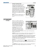
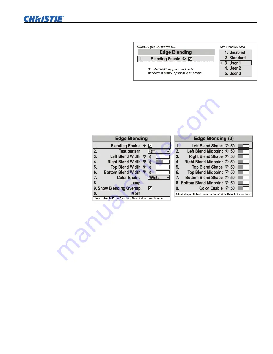
In the
Edge Blending
submenu, enable the top checkbox to activate all controls.
NOTE:
If the
optional
ChristieTWIST
module is
installed, a pull-
down list
replaces this
checkbox (see
right). Select the
desired user-defined blend created for your current warp; no further blending at
the projector is required. Or, to simply edge blending a non-warped flat image,
select “Standard” and continue with Step 3.
3.
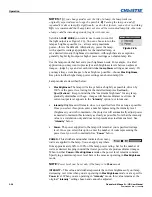
SET STARTING POINTS FOR ADJUSTMENT (Figure 3.38)
:
•
Set all blend widths to 0.
•
Go to “More” and set everything in the
Edge Blending (2)
menu to 50.
Figure 3.38. Set Starting Points for Each Projector
4.
SET BLEND WIDTH
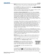
: On one projector, increase the
Blend Width
for an overlapping
edge (for example, if the projector’s image is on left, its right edge overlaps the
adjacent image—adjust
Right Blend Width
). Use the same setting on the second
projector for this shared edge.
5.
Re-adjust width (both projectors) until the overly bright band at the midpoint of
the overlapping blends disappears or
just
changes to very light gray. For the shared
edge, use the same
Blend Width
setting on each projector. If the best effect appears
to be between two settings, choose the wider setting for both projectors.
6.
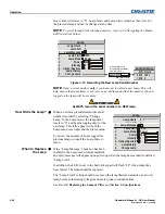
CHECK BLEND:
If the blended region appears too dark or light in relation to the
rest of the image:
•
Increase
Blend Midpoint
in both projectors to “lighten” the overall blend,
decrease to “darken” the overall blend.
•
Adjust
Blend Shape
in both projectors to fine-tune change the amount of mid-
gray intensity (as opposed to black/white) in the blend.
7.
Repeat with remaining projectors / overlaps.
8.
Check completed display wall with the desired external signal.
9.
Adjust mechanical alignment if necessary to maintain perfect pixel-on-pixel
alignment over time.

