


Appendix E
System Integration
Roadster & Mirage S+/HD User Manual
E-1
020-100002-04 Rev. 1 (12-2008)
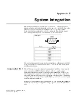
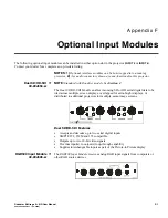
The GPIO (General Purpose Input/Output) connector located on the input panel
provides a flexible method of interfacing a wide range of external I/O devices to the
projector. There are seven GIO pins available on the nine-pin D-Sub GPIO
connector, which are configurable via RS232 commands. The other two pins are
reserved for ground and power – see table below for pin identification.
GPIO Pins
Pin #
Signal
1
+ 12V (200mA)
2 GPIO
1
3 GPIO
2
4 GPIO
3
5 Ground
6 GPIO
4
7 GPIO
5
8 GPIO
6
9 GPIO
7
The serial cable required for connecting the external device to the projector’s GPIO
connector, whether it’s a standard serial cable or a custom one, must be compatible
with the external device.
The GPIO connector can be configured to automate any number of events using the
serial command code
GIO
. Each pin is defined as either an
input
or
output
depending on the desired outcome. In general, configure the pin as an input if you
want the projector to respond to something the device does and as an output if you
want the external device to respond to an action taken by the projector. For example,
configure the pin as an output if you want the lighting in a room to automatically dim
when the projector is turned on.
By using the GIO command, you can also set the state of each pin as
high
or
low
. By
default, the state of each pin is
high.
The voltage applied to pins in the
high
state is +
3.3V.
Configuring the GPIO


