Chapter 17
17-58
T-17-50
11. SYSTEM
T-17-51
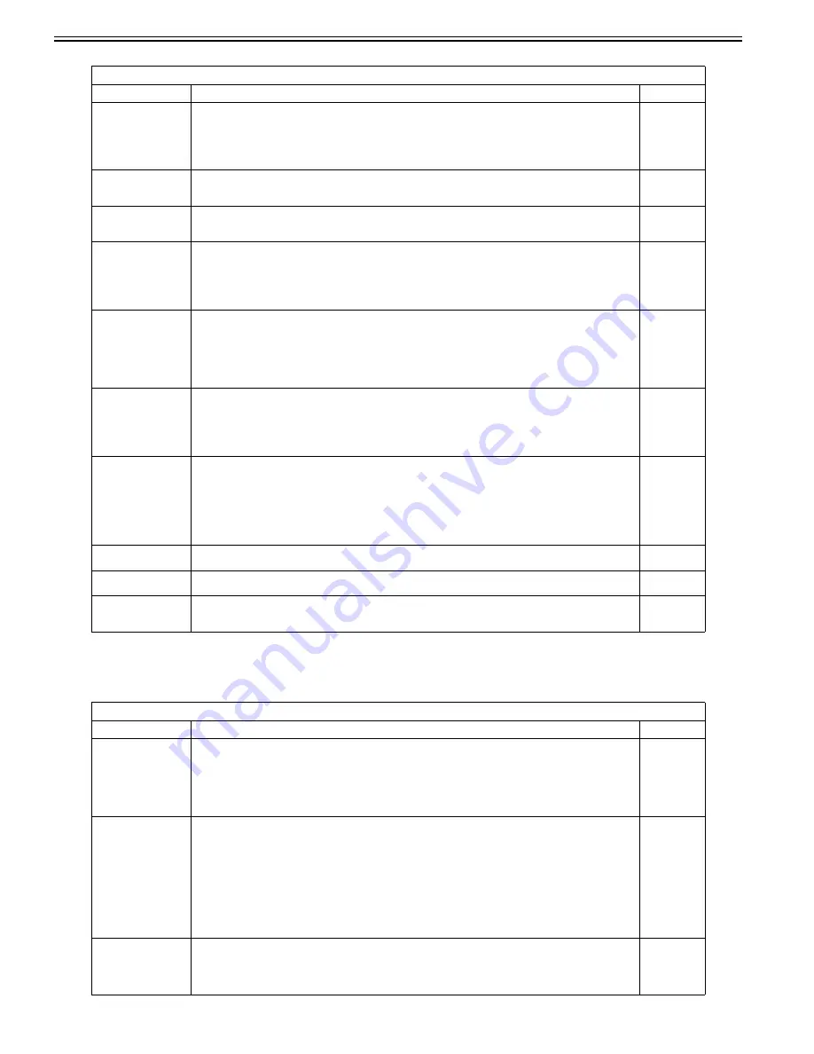
COPIER>FUNCTION>MISC-P
Sub item
Description
level.
P-PRINT
Prints service mode setting values.
Operation method
1) Select this item.
2) Press the OK key to print the setting values.
Reference:
Printing takes about 15 seconds to start.
1
KEY-HIST
- KEY-HIST (Prints the operation panel's key input history.)
1) Select this item.
2) Press the OK key to start printing.
1
HIST-PRT
- HIST-PRT (Prints the jam history and error history.)
1) Select this item.
2) Press the OK key to start printing.
1
USER-PRT
Prints user mode list.
Operation method
1) Select this item.
2) Press the OK key to print the list.
Reference:
Printing takes about 3 seconds to start.
1
LBL-PRNT
Prints service label.
Operation method
1) Place A4/LTR paper in the manual feed tray.
2) Select this item.
3) Press the OK key to print the label.
Reference:
Printing takes about 15 seconds to start.
1
D-PRINT
Printing out service mode (DISPLAY)
Procedure
1) Select this mode.
2) Press OK to print out.
Reference:
Only DISPLAY items are printed out. (Items of P-PRINT/LBL-PRINT/HIST-PRINT and ALARM are excluded.)
1
ENV-PRT
Outputting logs of inside machine temperature and humidity/fixing roller surface temperature
Procedure
1) Select this mode.
2) Press OK to output logs of inside machine temperature and humidity/fixing roller surface temperature.
Reference:
This mode is to output logs of [inside temperature(deg C)/humidity(%)/fixing roller surface (center) temperature (deg
C)] variations using signals of the attached temperature/humidity (environmental) sensor and fixing thermistor (main).
(Max. 100 records)
1
PJH-P-1
Prints print job history with detailed information (for 100 jobs).
Prints print job history with detailed information for last 100 jobs stored in copier main unit.
1
PJH-P-2
Prints print job history with detailed information (for all jobs).
Prints print job history with detailed information for all jobs stored in copier main unit.
1
TRS-DATA
- TRS-DATA (Moves the data received in memory to the BOX.)
1) Select this item.
2) Press the OK key to start printing.
1
COPIER>FUNCTION>SYSTEM
Sub item
Description
level.
DOWNLOAD
Switches to download mode.
Operation method
1) Select this item.
2) Press OK to enter download mode and have the copier wait for commands (wait for connection). ("STNDBY" is now
displayed, next to the DOWNLOAD sub-items.)
3) Use the service support tool to start downloading. ("CONNECTED"is displayed during communication with the PC.)
4) When communication ends, "HOLD"is displayed. (The power can be turned off when "HOLD"is displayed.)
1
CHK-TYPE
Used to specify partition number when performing HD-CHECK or HD-CLEAR.
Operation method
1) Select this item.
2) Use the numeric keypad to select the desired partition number.
0: Check and restore all bad sectors on hard disk
1: Image storage area
2: General-purpose file storage area
3: PDL file storage area
4: Firmware storage area
- General-purpose files include user-set data, log data, PDL spool data, and management information for image data.
3) Press the OK key.
1
HD-CHECK
Use it to check the entire HD and perform recovery.
Operation method
set '0' to the following: COPIER>FUNCTION>SYSTEM>CHK-TYPE
1) Select this item.
2) Press the OK key.
1
Summary of Contents for Color iR C3480
Page 2: ......
Page 27: ...Chapter 1 Introduction ...
Page 28: ......
Page 47: ...Chapter 1 1 18 F 1 14 ON OFF ON OFF ...
Page 70: ...Chapter 1 1 41 5 Turn on the main power switch ...
Page 79: ...Chapter 2 Installation ...
Page 80: ......
Page 85: ...Chapter 2 2 3 Not available in some regions ...
Page 134: ...Chapter 3 Basic Operation ...
Page 135: ......
Page 137: ......
Page 143: ...Chapter 4 Main Controller ...
Page 144: ......
Page 152: ...Chapter 4 4 6 F 4 6 CPU HDD ROM access to the program at time of execution ...
Page 171: ...Chapter 5 Original Exposure System ...
Page 172: ......
Page 203: ...Chapter 6 Laser Exposure ...
Page 204: ......
Page 206: ......
Page 220: ...Chapter 7 Image Formation ...
Page 221: ......
Page 277: ...Chapter 8 Pickup Feeding System ...
Page 278: ......
Page 282: ......
Page 336: ...Chapter 9 Fixing System ...
Page 337: ......
Page 339: ......
Page 357: ...Chapter 10 Externals and Controls ...
Page 358: ......
Page 362: ......
Page 366: ...Chapter 10 10 4 F 10 2 F 10 3 FM1 FM2 FM5 FM8 FM11 FM4 FM3 FM6 FM7 FM9 FM10 ...
Page 375: ...Chapter 10 10 13 F 10 10 2 Remove the check mark from SNMP Status Enabled ...
Page 376: ...Chapter 10 10 14 F 10 11 ...
Page 402: ...Chapter 11 MEAP ...
Page 403: ......
Page 405: ......
Page 452: ...Chapter 12 RDS ...
Page 453: ......
Page 455: ......
Page 464: ...Chapter 13 Maintenance and Inspection ...
Page 465: ......
Page 467: ......
Page 469: ...Chapter 13 13 2 F 13 1 8 9 1 2 3 3 5 6 7 10 11 12 13 14 4 ...
Page 474: ...Chapter 14 Standards and Adjustments ...
Page 475: ......
Page 477: ......
Page 485: ......
Page 486: ...Chapter 15 Correcting Faulty Images ...
Page 487: ......
Page 495: ...Chapter 15 15 4 F 15 2 COLOR M 1 COLOR Y C K 0 ...
Page 569: ...Chapter 15 15 78 F 15 82 J102 J107 J103 J108 J101 J109 J106 J112 J115 J113 J114 J104 J105 ...
Page 570: ...Chapter 16 Self Diagnosis ...
Page 571: ......
Page 573: ......
Page 600: ...Chapter 17 Service Mode ...
Page 601: ......
Page 603: ......
Page 712: ...Chapter 18 Upgrading ...
Page 713: ......
Page 715: ......
Page 746: ...Chapter 19 Service Tools ...
Page 747: ......
Page 749: ......
Page 752: ...APPENDIX ...
Page 774: ......


