background image

700 NDIR Analyzer 


6-20-2017 


43 


Zero   


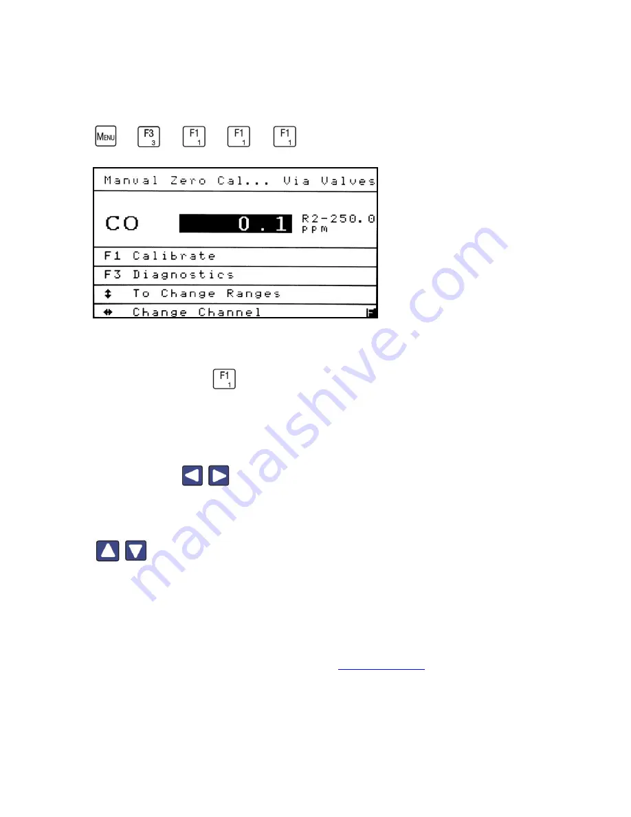
A Zero calibration should be performed before a span calibration. 

From the Manual 

Calibration menu press 

 to access the Manual Zero Calibration screen. 


If the analyzer is equipped with multiple channels, make sure you are calibrating the right 

component (CO shown above). If this is not the component you want to calibrate, use the 

Right/Left arrow 


 to change the channel to the desired component. 


Make sure the analyzer is in the range you wish to calibrate. Use the Up/Down arrows 


to go to the desired range. The screen illustration above shows the range (R2) 

next to the maximum range limit (250 ppm). 


In the upper-right corner of the screen, you will see a status line that indicates how the 

calibration gas is being introduced into the analyzer. In this case, Cal Via valves is 

displayed. The other option is Cal via Pump. See 

Calibration Setup

 for details.  


Summary of Contents for 700 NDIR

Page 1: ...700 NDIR Analyzer 6 20 2017 1 ...

Page 2: ...bration 48 Initiate Sequenced Cal 50 Initiate Sequenced Check 52 Cal Gas Concentrations 53 Calibration Setup 54 Auto Calibration Schedule 54 Auto Calibration Parameters 57 Calibration Via Pump Valves 59 Auto Calibration Check 60 Auto Calibration Timing 61 Deviation Limits 63 Maximum Calibration Error 64 Maximum Verifying Error 65 Analog Hold on Cal 66 Calibration Factors 67 Manual Deviations 68 Ze...

Page 3: ...ngs 102 Programmable Analogs 103 Output Assignments 104 Output Scaling 106 Output Adjustments 108 Programmable Digitals 110 Output Assignments 111 Output Hold Clear 114 TCP IP Parameters 117 Data Logging Time 118 Auto Start Settings 119 Clock Settings 121 Alarms Menu 122 Current Alarms 123 Alarm Log 124 Alarm Limits 126 Temperatures 127 Pressures 128 Voltages 129 Concentrations 130 Alarm Display O...

Page 4: ... General AK Requirements 151 Scan Commands 153 Control Commands 164 Configuration Commands 168 Modbus Protocol 174 MBAP Description 174 MBAP Header Description 175 Modbus Command Function Codes 176 Modbus Map 193 01H Single Read Coil 193 03H Read Floating Point 197 16H Write Floating Point 202 Warranty Statement 204 ...

Page 5: ...lifornia Analytical Instruments Technical Support for assistance We want you to be among our thousands of satisfied customers Description The 700 NDIR analyzer is based on the infrared absorption characteristics of gases The analyzer s oxygen channel utilizes either the paramagnetic or electrochemical fuel cell method to determine the percent level of oxygen contained in the sample gas Features Me...

Page 6: ...rehensive diagnostics CE Mark and ETL listed conforms to UL STD 61010 1 certified to CAN CSA C22 2 STD No 610610 1 1065 compliant configurations Options Paramagnetic or electrochemical oxygen channel Oxygen channel only configuration Internal sample pump Sample flow control Multiple sample inputs 19 rack mount slides Output options Voltage Current RS 232 AK protocol TCP IP Modbus and AK protocol ...

Page 7: ...the cell and is introduced into the front chamber of a two chamber infrared microflow detector The detector is filled with the gas component of interest and consequently the beam experiences further energy absorption This absorption process increases the pressure in both chambers The differential pressure between the front and rear chambers of the detector causes a slight gas flow between the two ...

Page 8: ...tter than 1 0 of Full Scale of factory calibrated ranges Noise Less than 1 of Full Scale of factory calibrated ranges Zero and Span Drift Less than 1 of Full Scale per 24 hours Sample Flow Rate 0 5 to 2 0 LPM Oxygen Analysis Method Paramagnetic or Electrochemical Fuel Cell O2 Ranges 0 1 paramagnetic only up to 0 100 O2 Full Scale four definable ranges O2 Response Time T90 2 seconds paramagnetic 16...

Page 9: ...to an important detail A CAUTION safety alert appears with information that is important for protecting your equipment and its performance A WARNING safety alert appears with information that is important for protecting you other people and equipment from damage Pay especially close attention to all warnings that apply to your application The symbol an exclamation point in a triangle precedes a ge...

Page 10: ...ard CAUTION or WARNING statement Some or all of the above symbols may appear in this manual or on the equipment This manual should be consulted whenever one of these symbols is encountered on the equipment ALWAYS REMOVE POWER BEFORE CONNECTING OR DISCONNECTING SIGNAL CABLES OR WHEN SERVICING THE EQUIPMENT ...

Page 11: ...shipping container your analyzer arrives in The shipping container and packaging are specially designed to protect the analyzer in transport If you ever need to return the analyzer to CAI for repair or any other reason the original shipping container and packaging should be used Reporting Damage Should there be any apparent damage to either the inside or outside of the instrument due to shipping o...

Page 12: ...igned for rack mounting Optional rack mount slides are available 6 Do not install the CAI 700 NDIR O2 analyzer near equipment that emits electromagnetic interference EMI NOTE A front and rear supporting brace or equivalent is required if the optional rack mount slides were not purchased The Power On Off switch is accessible from the rear of the analyzer only DO NOT mount the analyzer in a manner t...

Page 13: ...ch tube 3 Sample Gas outlet vent for exhaust of sample gas inch tube 4 28 pin output terminal strip Main 1 standard 5 Analyzer Cooling Fan 6 Power Entry module for power connection power switch fuse compartment 7 Serial connection to connect serial connector cable 8 Inlet Outlet Gas Connections for Additional Channels 9 28 pin output terminal strip Main 2 10 28 pin output terminal strip main 3 ...

Page 14: ...Shielded wiring is recommended for output signals Output Connections See the Analog and Digital Interface section of this manual for instructions for the various output selection options Shielded wiring is recommended for output signals Recommended Gases 1 Nitrogen or zero air in a pressurized cylinder 2 Standard span gas near full scale concentration with a nitrogen balance in a pressurized certi...

Page 15: ...If introduced through the sample port pressures should be as follows 1 Without sample pump pressure should be 10 25 PSIG 2 With sample pump no pressure 3 Low pressure configuration should be 3 7 PSIG Gas Handling Equipment Pressure regulators for zero gas air or N2 and span gas cylinders are required for gas analysis using the 700 NDIR O2 Analyzer Gas Connections If the calibration gases are not c...

Page 16: ...n and takes all appropriate precautions The 700 NDIR O2 Analyzer s sampling system consists of 1 An internally mounted in line particulate filter 2 A sample pump and flow meter optional 3 A sample capillary that controls the sample flow rate to the sensor at 0 5 LPM 4 A precision controlled relief valve The relief valve maintains a constant inlet pressure to the sample capillary and reduces respon...

Page 17: ...eful service life of the instrument will be shortened if high concentrations of corrosive gases such as Cl2 SO2 F2 HCl etc are present in the sampled gas Gas Temperature When measuring high temperature gases make sure that the maximum temperature rating of the instrument 104ºF 50ºC is not exceeded Pressure and Flow Rates If the analyzer is using the optional sample pump do not introduce a pressuri...

Page 18: ...8 Sample Gas Bypass Outlet and Vent A sample gas bypass outlet connector is located on the analyzer s rear panel inch tube Pressure at this outlet should be kept at atmospheric level ANY backpressure will cause an error in reading ...

Page 19: ...eck the power source and the fuse If the problem persists call CAI Technical Support Refer to the Using the Keypad section and review the complete Operator s Manual for detailed instructions for proper setup and operation of the 700 NDIR O2 Analyzer Shutdown Procedure 1 Turn off the valves on the zero span and air cylinders 2 If the analyzer contains the optional internal sample pump disconnect th...

Page 20: ...shipping box was retained the analyzer should be stored in the box in the packing material supplied If the original box is not available and another appropriate box cannot be obtained the analyzer can be placed in a clean dry plastic bag Storage should be in a reasonably temperature controlled environment and away from any possible exposure to dust and water or other liquids ...

Page 21: ...eric values This is why each number key includes both the larger Function number at the top for example F1 and the smaller number underneath for numeric value for example 1 The Light key is used to turn the display s backlight on and off The Decimal Point key is used to enter a decimal point when a numeric value is keyed in The Menu key is used to bring you to the Main Menu at any time The Back ke...

Page 22: ...e displayed in the bottom right corner of the screen when the analyzer is in Numeric Entry mode An F is displayed when the analyzer is being used for Function mode In Function mode the arrow keys move the highlight Press the Enter key to accept the highlighted function In Numeric mode these keys control the cursor Arrow key functions will vary as is shown on some screens In Numeric mode the left a...

Page 23: ...n of the CAI 700 NDIR O2 Analyzer Start by pressing to access the Main Menu to quickly find any screen Menu Main Menu F1 Measure F2 Change Channel F1 Channel 1 F2 Channel 2 F3 Channel 3 F3 Menus F1 Calibration F2 Range Setup F3 Diagnostics F4 Setup F5 Alarms F6 Service F7 Security F4 Analyzer Info F5 Remote Manual F1 Manual F2 Remote F6 Standby ...

Page 24: ...alog Hold on Cal F5 Calibration Factors F1 Manual Deviations F2 Auto Cal Deviations F3 Offset Gain Factors F6 Reset Factory Settings F1 Reset Offset and Gain F2 Reset Linear Coefficients F1 Cal via Pump F2 Cal via Valves F1 Max Calibration Error F2 Max Verifying Error F1 Zero Gas Deviations F2 Span Gas Deviations F2 Verifying Span Devs F1 On F2 Off Security Level 1 STANDARD Security Level 2 SETUP ...

Page 25: ...tup Menu Main Menu F3 Menus F2 Range Setup F1 Range Limits F2 AutoRange On Off F1 Channel 1 F2 Channel 2 F3 Channel 3 F3 AutoRange Switch Points Security Level 3 FACTORY Security Level 2 SETUP Security Level 1 STANDARD Security Level Legend ...

Page 26: ...nu F3 Menus F3 Diagnostics F1 Diagnostic Values F1 Temps Press EPC Flows F2 Raw Value Display F3 I O Status F1 Analyzer Digital Outputs F2 Analyzer Digital Inputs F3 Programmable Digital Outputs F4 Status Line F1 Turn Status Line On F2 Turn Status Line Off ...

Page 27: ...2 Output Settings F1 Programmable Analogs F1 Output Assignments F2 Output Scaling F3 Output Adjustments F2 Programmable Digitals F1 Output Assignments F2 Output Hold Clear F1 Hold Outputs F2 Clear Outputs F3 Output Test F3 TCP IP Parameters F4 Data Logging Time F5 Auto Start Settings F6 Clock Settings Security Level Legend Security Level 1 STANDAR D Security Level 2 SETUP Security Level 3 FACTORY ...

Page 28: ...Current Alarms F2 Alarm Log F3 Alarm Limits F1 Temperatures F2 Pressures F3 EPC Voltages F4 Concentrations F4 Alarm Display On Off F1 Turn Alarm Display On F2 Turn Alarm Display Off Security Level Legend Security Level 1 STANDARD Security Level 2 SETUP Security Level 3 FACTORY ...

Page 29: ...rvice Menu Main Menu F3 Menus F6 Service F1 Linear Coeficients F1 Range 1 F2 Range 2 F3 Range 3 F4 Range 4 F2 Factory Service CAI use Only Security Level Legend Security Level 1 STANDARD Security Level 2 SETUP Security Level 3 FACTORY ...

Page 30: ... Main Menu F3 Menus F7 Security F1 Operator Levels F1 Standard Functions F2 Setup Functions F3 Factory Functions F2 Change Password F3 Reset Password Security Level Legend Security Level 1 STANDARD Security Level 2 SETUP Security Level 3 FACTORY ...

Page 31: ...unctions of the Series 700 NDIR O2 Analyzer can be reached via the menu above from the Main Menu screen Operation starts by pressing the Menu key to bring up the Main Menu Use the Arrow keys to highlight the desired function and press to open the screen You can also access the desired function by pressing the corresponding function key AK Status ...

Page 32: ...700 NDIR Analyzer 6 20 2017 32 ...

Page 33: ...ase review the descriptions below corresponding with the callouts on the illustration above to familiarize yourself with the Measure Screen Screen Name The name of the active screen the Analyzer is in in this case the Measure screen Second Log On SEC appears when the Second log is enabled See Data Logging Time Component Name Screen Name Measured Concentration Current Range Second Log On AK Status ...

Page 34: ...f the range currently in use Current Time Active Alarms Scrolls between Time and Date and any active alarms Keypad Status Indicates how the keypad input is currently being used F is for functions N is for numeric input DIL Indicates dilution software has been factory enabled Up and down arrows are used to change the analyzer s current range Shortcut Menu Scrollable list of shortcut functions avail...

Page 35: ...u Menus The Menus screen is the starting point for advanced setup and functions Standby When the analyzer is in Standby mode it closes all valves and turns off the analyzer s optional sample pump Range Limits This screen allows operators to customize the analyzer s ranges Span Conc Operators can change Span gas concentrations for multiple ranges Comp Factors This is a shortcut for operators to vie...

Page 36: ... used to select a component when using menus with analyzers that have multiple channels The Change Channel menu is accessed by pressing the key on the Main Menu Press to set control of Channel 1 Press to set control of Channel 2 Press to set control of Channel 3 Current Status ...

Page 37: ...s accessed by pressing the key on the Main Menu This screen includes the Model and Serial Number of your analyzer for easy identification if you are discussing your analyzer with CAI factory settings for sample pressure and air pressure and the software versions being used The analyzer s current IP address appears in the upper right corner of the screen ...

Page 38: ...te Manual menu is accessed by pressing the key on the Main Menu The current setting Remote Mode is displayed in the upper right hand corner of the screen Example SREM The analyzer can be controlled remotely via TCP IP Modbus RS 232 AK Protocol Digital inputs contact closure located on the rear of the analyzer AK Protocol works with both TCP IP and Serial Modbus only works with TCP IP ...

Page 39: ... 39 Standby or When the analyzer is in Standby Mode the pump is turned off and the solenoid valves are closed The CAI logo is displayed along with the Serial Number Standby Mode is accessed by pressing the key from the Main Menu ...

Page 40: ...on Setup and Diagnostics From the Main Menu press to bring up the Menus screen Press to access the Calibration menus Press to access the Range Setup menu Press to access the Diagnostics menus Press to access the Setup menus Press to access the Alarms menu Press to access the Service menu Press to access the Security menu ...

Page 41: ... Calibration menu includes important features including basic setup for both manual and automated calibration Preparing the Analyzer for Calibration NOTE If you are changing the analyzer s factory settings Calibration Setup must be completed prior to your initial calibrations From the Calibration menu press to access the Calibration Setup or you can use this menu path to access the Calibration Set...

Page 42: ...rformed before any of the span calibrations as long as they are within the same relatively short time period If multiple ranges are used the calibrations are typically done in ascending order of range Anytime a zero calibration is performed a span calibration or check should be done afterward The Manual Calibration menu is accessed by pressing from the Calibration menu Press to access the Manual Z...

Page 43: ...t to calibrate use the Right Left arrow to change the channel to the desired component Make sure the analyzer is in the range you wish to calibrate Use the Up Down arrows to go to the desired range The screen illustration above shows the range R2 next to the maximum range limit 250 ppm In the upper right corner of the screen you will see a status line that indicates how the calibration gas is bein...

Page 44: ...y are within their limits If all diagnostic values are within their limits press the button to return to the Manual Zero Calibration screen When the concentration value has stabilized press to set the zero calibration The zero portion of the calibration should now be complete If the calibration was successful the screen will say Saved Current above the concentration value Example of a successful c...

Page 45: ...ck the following 1 Make sure the correct gas was introduced into the analyzer 2 Verify the Diagnostic Values while flowing gas 3 Check Zero Gas Deviations under Manual Deviations 4 Check Maximum Calibration Error under Calibration Setup After a successful Manual Zero Calibration press the button to return to the Manual Calibration menu The analyzer is now ready for a span calibration or check ...

Page 46: ...ficate press and change the concentration to match it Press again to close the span gas concentration field Make sure the analyzer is in the range you wish to calibrate Use the Up Down arrows to go to the desired range The illustration shows the range R1 next to the maximum range limit 100 ppm Introduce span gas into the rear of the analyzer Press to go to the Diagnostic Values screen to view the ...

Page 47: ...viation Limits See the Manual Zero Calibration section for examples of screens showing successful and unsuccessful calibrations If the span calibration is unsuccessful check the following 1 Make sure the correct gas was introduced into the analyzer 2 Verify the Diagnostic Values while flowing gas 3 Check Span Gas Deviations under Manual Deviations 4 Check Maximum Calibration Error under Calibratio...

Page 48: ...libration menu Sequenced means that the flow times of both zero and span gases are controlled using a timer See AutoCal Timing located in the Calibration Setup menu NOTES An automated calibration should not be attempted before manual zero and span calibrations have been successfully performed If a manually initiated sequenced calibration or sequenced calibration check is selected it will apply onl...

Page 49: ...enced calibration can be preset to include the desired interval for recurring analyzer initiated calibrations This requires additional setup Automatic calibration of multiple ranges is also possible See Calibration Setup If a sequenced calibration was unintentionally started pressing the button before the Zero step is completed will cancel the calibration ...

Page 50: ...er set up in AutoCal Timing located in the Calibration Setup menu The sequence with the current range indicated is as follows 1 Zero Range 1 Purging Allows time for the zero gas to flush out any residual gases that may still be present in the detection path 2 Zero Range 1 Calibrating The calculated zero is set as the new offset value as long as it is within the Maximum Calibration Error limits 3 Z...

Page 51: ...tion is successful the display will briefly indicate Calibration Finished in place of Calibration in Progress at the top of the screen After a successful calibration is completed the analyzer will return to the Measure Screen If the calibration is unsuccessful the display will briefly indicate Could Not Calibrate in the Current Status line At the same time you will be alerted to whether an error o...

Page 52: ...libration Menu screen pressing initiates a sequenced calibration check Rather than initiating a calibration it checks the validity of your most current calibration A sequenced calibration check performs all of the steps of a sequenced calibration with the exception of the zero and span calibrations It does not set new offsets gains or any alarms ...

Page 53: ...full scale value set for that range If the analyzer is equipped with multiple channels make sure you are calibrating the right component CO shown above If this is not the component you want to calibrate use the Right Left arrow to change the channel to the desired component Using the Up Down arrows move the highlighted field to the span gas value you wish to change for example 95 00 above Press to...

Page 54: ...ation Setup menu apply to Automated Calibration The following also apply to Manual Calibration Cal Pump Valves Auto Cal Check Deviation Limits and Analog Hold on Cal All settings should be verified for correct information before a manual or automated calibration is attempted Please note that the Calibration Setup menu shows the current settings on the right side of the screen after the ellipsis Ex...

Page 55: ...can be changed by the operator The Auto Calibrations screen is accessed by pressing from the Calibration Setup menu Use the arrow buttons to move the highlight to changeable fields in the example Start Time 12 Press to open the field and change the value Press again to close the field after you have made your changes Screen Name Scheduled Calibration Interval Next Scheduled Calibration Time and Da...

Page 56: ...e made and the analyzer will revert to the previous settings To change Timed Auto Calibration to on or off press Timed Cal On Off A submenu will open with two choices Press to turn Timed Cal On or press to turn Timed Cal Off Selecting or will bring you back to the AutoCal Schedule screen The current setting is shown on the right side of the menu after the ellipsis In the example Timed Cal On Off O...

Page 57: ...ld you intend to change Press to open the field and change the parameter Press again to close the field after you have made your change The first changeable parameter is the Range to be calibrated Press to open the field and change the range Then select a range from 1 4 for calibration To select all ranges press 0 Press to close the field The second parameter the operator can change is the Channel...

Page 58: ... with Zero gas only or All calibration gases zero and span gases Press to open the field and change the parameter using the up down arrows Press to close the field Press to save your settings Once your changes have been saved the analyzer will return you to the Calibration Setup menu ...

Page 59: ...alibration Setup Menu Please note that the Calibration Setup menu will display the current settings on the right side of the screen after the ellipsis Example Cal Pump Valves Pump NOTE If the analyzer is equipped with a pump to prevent damage to the pump do not pressurize the sample inlet Press Cal via Valves to activate the appropriate calibration valve and keep the internal sample pump turned of...

Page 60: ...ess to set the analyzer parameter to Calibrate This setting will be saved and the analyzer will return to the Calibration Setup menu The Calibration Setup menu shows the current setting on the right side of the screen after the ellipsis Example Auto Cal Check Cal Press to set the analyzer parameter to Check The setting will be saved and the analyzer will return to the Calibration Setup menu The Ca...

Page 61: ...or right arrow keys to select the desired component To navigate between parameters use the up or down arrow to move the highlight to the field you intend to change Press to open the field and change the value seconds Press again to close the field after you have made your change A sequenced auto calibration consists of two cycles Zero and Span In both cases the cycle duration is equal to the sum o...

Page 62: ...seconds and cannot be changed by the operator 3 Verifying Time during this time the measured value is checked to make sure it does not deviate outside the upper or lower limit specified by the Maximum Verifying Error The verifying time is typically set for 10 seconds 4 Purge After the operator can set the time needed to flush any remaining calibration gases out of the analyzer before the In Cal St...

Page 63: ...fine the maximum acceptable error limits of the zero and span gases for both manual and sequenced calibration To access the Deviation Limits menu press from the Calibration Setup menu Press to set or view the Maximum Calibration Error Limits Press to set or view the Maximum Verifying Error Limits ...

Page 64: ...imum Calibration Error screen press from the Deviation Limits menu Use the left or right arrow keys to select the component you wish to view or change To navigate between fields use the up or down arrow keys to move to the highlight to the field you intend to change Press to open the field to change the allowable tolerance in Press again to close the field Press to save your changes Absolute Devia...

Page 65: ...erifying Error screen press from the Deviation Limits menu Use the left or right arrow keys to select the component you wish to view or change To set the allowable tolerances for different ranges use the up or down arrow to move the highlight to the field you intend to change Press to open the field to change the value in Press again to close the field Press to save your changes ...

Page 66: ... Analog Hold On Cal menu press to turn Analog Hold On which will hold the analog outputs at the last measured value You will return to the Calibration Setup menu The Calibration Setup menu shows the current setting at the bottom right corner of the screen after the ellipsis Example Analog Hold on Cal On From the Analog Hold On Cal menu press to turn Analog Hold Off You will return to Calibration S...

Page 67: ...o track and view changes from the factory and previous calibrations To access the Calibration Factors menu press from the Calibration menu Press to view the Manual Calibration Deviations menu Press to view the Auto Calibration Deviations menu Press to access the Offset and Gain Factors screen ...

Page 68: ...he Manual Deviations menu allows the operator to view the Zero and Span Deviations from manual calibrations Press from the Calibration Factors menu to access the Manual Deviations menu Press to view Zero Gas deviations Press to view Span Gas deviations ...

Page 69: ...he left or right arrow keys to select the component you wish to view Absolute Zero Gas Deviation is the zero gas content calculated by the factory polynomial related to the calibrated range limit Relative Zero Gas Deviation is the current deviation minus the deviation of the previous calibration related to the calibrated range limit ...

Page 70: ...en Use the left or right arrow keys to select the component you wish to view Absolute Span Gas Deviation is span gas bottle value minus span gas value calculated by the factory polynomial related to the calibrated range limit Relative Span Gas Deviation is the current deviation minus the deviation of the previous calibration ...

Page 71: ...wing either zero or span verifying deviations The verifying deviations are taken during the verifying stage of sequenced and auto calibrations Press from the Calibration Factors menu to access the Auto Cal Deviations menu Press to view the Verifying Zero Deviations screen Press to view the Verifying Span Deviations screen ...

Page 72: ...eviations screen Use the left or right arrow keys to select the component you wish to view Measured Value is the averaged concentration during the Verifying Zero stage of sequenced and auto calibrations Variance is the difference of the measured value and zero FS is the percent of full scale related to the calibrated range limit ...

Page 73: ... screen Use the left or right arrow keys to select the component you wish to view Measured Value is the averaged concentration during the Verifying Span stage of sequenced and auto calibrations Variance is the difference of the measured value and span gas concentration FS is the percent of full scale related to the calibrated range limit ...

Page 74: ...sight into changes in analyzer performance Press from the Calibration Factors menu to access the Offset Gain Factors screen Use the left or right arrow keys to select the component you wish to view Offset is the difference between factory zero and the value stored during zero calibration Gain is the value stored during span gas calibration using the operator defined calibration gas ...

Page 75: ...r a choice of resetting the Offsets and Gains or both Factory Linear Coefficients and Offsets and Gains for all calibrated ranges Resetting factory settings will not affect any other operator changed parameters Press to reset the Offsets and Gains Press to reset the Linear Coefficients Offsets and Gains ...

Page 76: ...ht arrow keys to select the component you wish to reset Pressing Yes from this screen resets the Offset and Gain factors to factory default settings 0 and 1 respectively and brings you to this confirmation screen Offset and Gain factors are created when the analyzer is zeroed and spanned If the Offsets and Gains are reset the analyzer must be zeroed and spanned again before use All recorded deviat...

Page 77: ...700 NDIR Analyzer 6 20 2017 77 If you press No from the Reset Offsets and Gains screen the analyzer will return to the Reset Factory Settings menu without resetting the Offsets and Gains ...

Page 78: ...Coefficients for all ranges Use the left or right arrow keys to select the component you wish to reset Pressing Yes from this screen resets all the Linear Coefficients Offset and Gain Factors to factory default settings and brings you to this confirmation screen NOTE After resetting Linear Coefficients the analyzer must be zeroed and spanned before further use ...

Page 79: ...R Analyzer 6 20 2017 79 If you press No from the Reset Linear Coefficients screen the analyzer will return to the Reset Factory Settings menu without resetting the Linear Coefficients Offsets and Gains Factors ...

Page 80: ...m the Menus screen press to access the Range Setup menu Press to view or change Range Limits Press to access the Auto Range On Off menu In either case you will return to the Range Setup menu The Range Setup menu shows the current status on the right side of the screen after the ellipsis Example AutoRange On Off Off Press to view or change Auto Range Switch Points ...

Page 81: ...select the component you wish to view or change To change the Range Limits from the factory settings use the up or down arrows to move the highlight to the field you intend to change Press to open the field to change the value in ppm Press again to close the field Press to save your changes To initiate the saved changes press then press and select new ranges NOTES 1 If Ranges are factory linearize...

Page 82: ...mple Maximum Range Limit 20 000 4 To set a single range set Range 1 to the desired value and all others to zero 5 To set two ranges set Range 1 to the lowest value Range 2 to the highest value and the others to zero 6 If new ranges are saved the Auto Range Switch Points will be set to default percentages of range limits See Auto Range Switch Points ...

Page 83: ...rs in the upper right corner of the screen Use the left or right arrow keys to select the component you wish to view or change Press to turn Auto Range On This function allows the analyzer to automatically change ranges without the presence of an operator Press to turn Auto Range Off When Auto Range is Off the operator will need to manually change the ranges The Range Setup menu shows the current ...

Page 84: ... previous range s Up Switch Point Press the key to select the component you wish to view or change To change the Auto Range Switch Points use the up down arrows to move the highlight to the field you intend to change Press to open the field to change the value in ppm Press again to close the field Press to save your changes To initiate the saved changes press then press and select new Auto Range S...

Page 85: ...cess the Diagnostic Values screen It allows you to check analyzer temperatures pressures EPC voltage percentages and flows Press to access the Raw Values Display menu Press to access the I O Status menu You can check the status Open or Closed of the analyzer s digital outputs and inputs Press to turn On or Off the AK Status Line The current setting is shown on the Diagnostics menu on the right sid...

Page 86: ...isplays the current temperature and low and high alarm limits for key analyzer components As indicated at the bottom of the screen use the left and right arrow keys to scroll to different screens The current screen will be highlighted Temps in the example The Temperatures Pressures and EPC Voltage Percent screens include the current device Values and the Low and High Alarm Limits For example if th...

Page 87: ...re across the flow orifice along with low and high alarm limits in PSI EPC Voltage Percent Screen The EPC screen displays the percentage of EPC voltage being supplied to the EPC valve along with external 1 and 2 voltages External 1 and External 2 are used by factory for gas and humidity compensation when equipped ...

Page 88: ...er 6 20 2017 88 Flows Screen The Flows screen displays the current flow of sample and air in L minute It does not include an alarm function because flows are calculated values based on the pressures across an orifice ...

Page 89: ...r to generate the calibration curve from which the Raw Concentration and Measured Concentration are derived The 0 512 volts is equal to 0 ppm and 4 512 volts is equal to the highest factory set range limit of that component Raw Concentration This value in engineering units is calculated from the Raw Volts before linearization and offset and span corrections are applied Measured Concentration This ...

Page 90: ...and analyzer is set to Cal via Valves Zero will be indicated above the range at the bottom right of the screen To return to the Measure mode press F4 again Meas will be indicated above the range on the screen Press to open the Span valve if your analyzer is equipped with optional calibration valves and analyzer is set to Cal via Valves Span will be indicated above the range at the bottom right of ...

Page 91: ...of the analyzer s digital outputs or digital inputs open or closed To access the I O Status menu press from the Diagnostics menu Press to view the status of the analyzer s standard digital outputs Press to view the status of the analyzer s digital inputs Press to view the status of the Programmable Digital Outputs ...

Page 92: ...r that are used to control the digital output function In the example M7 M is the Main Connector on the analyzer s back panel and 7 is the Pin Number on that connector The Status becomes closed when the function is true In the example above the analyzer is in Range 4 Range 4 s status is closed This will result in a closed contact to digital ground It can be measured from the Main Connector Pin 6 d...

Page 93: ...fferent Analyzer Digital Input screens The Pin column indicates the connector and the pin number that are used to control the function In the example M12 M is the Main Connector on the analyzer s back panel and 12 is the Pin Number on that connector The abbreviations are as follows M Main Connector A Auxiliary Int Internal for CAI use only When the analyzer is in Remote Mode and the digital input ...

Page 94: ...ses As indicated at the bottom of the screen press the left and right arrow buttons to view the next or previous page of Programmable Digital Output statuses The column key is as follows Aux Pin Auxiliary connector on the back panel and pin number on the connector DO Programmable digital output number Function Operator programmed function Status The state the programmed relay is in open or closed ...

Page 95: ... Protocol information See AK Protocol The current status is shown in the upper right corner of the Status Line menu Example above OFF From the Diagnostics menu press to select On or Off Press from the Status Line menu to turn the AK Status Line On Press from the Status Line menu to turn the AK Status Line Off Example of the Status Line turned on K3 SREM ...

Page 96: ...up screens allow the operator to view or change Averaging times and compensation factors Press to access the Output Settings menu The Programmable Analog and Programmable Digital outputs can be viewed or set up to fit the operator s needs Press to view or change the current TCP IP parameters Press to access the Data Logging Time screen For CAI use only Press to view or make changes to the Auto Sta...

Page 97: ...p parameters Averaging Time and Compensation Factors The Measure Settings menu is accessed by pressing from the Setup menu Press to view or change the Averaging Time of the measured concentration Press to view or change Compensation Factors Press to view or set the Dilution ratio settings Special software option ...

Page 98: ...tings menu press to access the Averaging Time screen The Averaging Time is a sliding average As shown above it can be set from 0 60 seconds Press to open the field to change the time After making your change press again to close the field Press to save your changes and restart the averaging of the measured concentration You will return to the Measure Settings menu ...

Page 99: ...700 NDIR Analyzer 6 20 2017 99 Comp Factors or ...

Page 100: ...700 NDIR Analyzer 6 20 2017 100 T P Compensation H2O Compensation ...

Page 101: ...700 NDIR Analyzer 6 20 2017 101 Gas Compensation ...

Page 102: ... The Output Settings menu is accessed by pressing from the Setup menu Press to see the Programmable Analogs menu which allows the operator to view or change the analog Output Assignments Output Scaling or make Output Adjustments Press to see the Programmable Digitals menu which allows the operator to view or change the Digital Output Assignments choose Output Hold or Clear or conduct an Output Tes...

Page 103: ...nu is accessed by pressing from the Output Settings menu Press to view or reassign the four programmable analog output signals Press to view or set the output scaling of programmable analog output signals Press to set or adjust the analog outputs The operator can set the output to either current or voltage and calibrate the outputs to exactly match the results obtained on a PLC or other remote dat...

Page 104: ...u intend to change Press to open the field and use the Up Down arrows to change it to the desired signal Press again to close the field Press to save your changes NOTES 1 Analog Output 1 for example is listed as AO 1 in the Output column 2 For information on analog output connections see Analog and Digital Interface The following output signals can be programmed by the operator using the Output As...

Page 105: ...ure Barometric pressure measured at output of Channel1 Temp Internal analyzer case temperature Temp Ch1 Temperature of channel 1 detector Temp Ch2 Temperature of channel 2 detector Temp Ch3 Temperature of channel 3 detector EPC Ch1 of voltage supplied to open Cannel 1 EPC if equipped with flow control EPC Ch2 of voltage supplied to open Cannel 1 EPC if equipped with flow control EPC Ch3 of voltage...

Page 106: ...aling of temperatures or pressures but it can also be used to set an output for a specific concentration From the Programmable Analogs menu press to access the Output Scaling screen Use the Up Down arrows to highlight the field you intend to change Press to open the field to change the value After making your change press again to close the field Press to save your changes and return to the Progra...

Page 107: ...er settings are 0 00 and 0 00 the default settings allow the output voltage to follow the range limits Example If Range 1 is set to 10 ppm and Range 2 is 100 ppm in Range 1 10 ppm will 10 VDC and in Range 2 100 ppm will 10 VDC 3 When the analog Output Assignment is set for concentrations and the lower setting is set to 0 00 and the upper setting is set to 10 00 the output will no longer follow the...

Page 108: ...e and back to Measure For information on analog output connections see Analog and Digital Interface From the Programmable Analogs menu press to access the Output Adjustments screen Output Type can be set for mA or 1 5 or 10 VDC Output AO 1 refers to analog output 1 FS is used to toggle between Measurement 0 50 and 100 Full Scale Offset zero is used to adjust the output at 0 Gain span is used to ad...

Page 109: ...to the FS column and press until the FS column value reads 100 0 Then use the Left Right arrows to highlight the Gain column Press to open the field Make a small adjustment and press again to close the field and check the output Repeat this procedure as necessary for other outputs When you are finished making all your changes press to save them You will return to the Programmable Analogs menu NOTE...

Page 110: ...enu is accessed by pressing from the Output Settings menu From the Programmable Digitals menu Press to assign any of the 15 programmable digital outputs to a specific alarm or status Press to set the programmable digital alarms to hold or clear after the alarm is gone The current Output Hold Clear status is shown on the right side of the Programmable Digitals screen after the ellipsis Example Outp...

Page 111: ...ssignments screen Use the left and right arrow buttons to highlight the field you intend to change Press to open the field and use the up or down arrow button to change the signal Press again to close the field Press to save your changes NOTES 1 For information on digital output connections see Analog and Digital Interface 2 Alarms go open when present and statuses go closed when active 3 See the ...

Page 112: ...ot calibrated 1LoC Channel 1 conc 1 2LoC Channel 2 conc 1 3LoC Channel 3 conc 1 1HiC Channel 1 conc 2 2HiC Channel 1 conc 2 3HiC Channel 1 conc 2 1DT Ch1 Detector temperature 2DT Ch2 Detector temperature 3DT Ch3 Detector temperature 1EV Ch1 EPC Voltage 2EV Ch2 EPC Voltage 3EV Ch3 EPC Voltage 1OR Ch1 Over Range 2OR Ch2 Over Range 3OR Ch3 Over Range 1AU Ch1 ADC Under Range 2AU Ch2 ADC Under Range 3A...

Page 113: ...h3 in Range 1 3R2 Ch3 in Range 2 3R3 Ch3 in Range 3 3R4 Ch3 in Range 4 3IC Ch3 in Calibration 3Z Ch3 in Zero 3S Ch3 in Span 3SA Ch3 in Sample General Alarms__________________________________________________________ Channel 1 Flow Channel 2 Flow Channel 3 Flow External 1 External 2 Output Pressure Baro Analyzer Temperature Ch1 Detector temperature Ch2 Detector temperature Ch3 Detector temperature C...

Page 114: ... The Output Hold Clear menu is accessed by pressing from the Programmable Digitals menu Press to hold programmed alarm outputs until they are manually cleared Press to set the outputs to automatically clear when alarms are no longer present NOTES To manually clear held alarms press from this menu An output alarm cannot be cleared until the alarm is back within its limits Once the outputs are clear...

Page 115: ...by pressing from the Programmable Digitals menu The Output Test Warning screen first appears asking if you wish to continue the output test If you proceed with the test you must reboot the analyzer to exit the output test To exit the Output Test screen and proceed with normal operation press To continue to the Output Test screen press For information on output connections see Analog and Digital In...

Page 116: ...change the state of the output open or closed Press again to change the state back To test all the outputs at once press to change the state of all the outputs they are all Open in the example Press again to change all the output states back Upon completion of the test you will be required to reboot the analyzer to resume operation ...

Page 117: ...ternet Protocol specifies the addressing scheme Most networks combine IP with TCP establishing a virtual connection between destination and source The IP address Netmask and Gateway may be defined by the user The Port and WinIfPort are assigned 7700 and 2000 by CAI and should not be changed unless required for a certain location Use the Up Down arrows to move the highlight to the setting you wish ...

Page 118: ...o turn this feature on These files can only be accessed by CAI To access the Data Logging screen press from the Setup menu To turn Data Logging on press to open the field and change the Logging Interval from 0 to the desired time in seconds After making your change press again to close the field Press to save your change and return to the Setup menu To turn Data Logging off change the interval to ...

Page 119: ...ings the analyzer was last in The operator can set the following parameters Startup Mode The analyzer can be set to start up in Standby or Measure mode Auto Startup Turn the Auto Startup function on or off Wait for min Allow for the time it takes for the analyzer to warm up before calibration Access Level Select the Operator Security Level Remote Manual Set whether the analyzer starts up in Remote...

Page 120: ...a setting use the Up Down arrows to move the highlight to the setting you wish to change Press to open the field to change the value After making your change press again to close the field Press to save your changes and return to the Setup menu ...

Page 121: ...uto calibrations and data time stamping The Clock Settings screen is accessed by pressing from the Setup menu To change a setting use the Up Down arrows to move the highlight to the setting you wish to change Press to open the field to change the value After making your change press again to close the field Press to save your changes and return to the Setup menu ...

Page 122: ...w the alarms that are currently active Press to access the Alarm Log The operator can view a log of the last 40 alarms Press to access the Alarm Limits menu The operator can view or change the existing alarm limits Press to turn On or Off the display of the active alarms that scroll across the bottom of the Measure screen The current setting is shown on the Alarms menu on the right side of the scr...

Page 123: ...Over Range AirP Air Pressure AUnd ADC Under Range OvenT Oven Temperature R1NC Range 1 not calibrated ConvT NOx Converter Temperature R2NC Range 2 not calibrated PumpT Pump Temperature R3NC Range 3 not calibrated DiodT Diode Temperature R4NC Range 4 not calibrated CellT Cell Temperature O2NC O2 not calibrated DryT Dryer Temperature Conc1 Concentration Alarm 1 O2T Oxygen Det Temperature Conc2 Concen...

Page 124: ...yzer s last 40 alarms and their current statuses Press to access the Alarm Log screen from the Alarms menu Press to view the next page Press to return to the previous screen Alarm Abbreviations and Descriptions Screen Name Year Month Day Hour Minute Alarm Abbreviation Alarm Value Alarm Status ...

Page 125: ...ot calibrated PumpT Pump Temperature R3NC Range 3 not calibrated DiodT Diode Temperature R4NC Range 4 not calibrated CellT Cell Temperature O2NC O2 not calibrated DryT Dryer Temperature Conc1 Concentration Alarm 1 O2T Oxygen Temperature Conc2 Concentration Alarm 2 SEPC Sample EPC Voltage O2ADC O2 ADC Alarm AEPC Air EPC Voltage O2Conc1 O2 Concentration Alarm 1 ROvr Over Range O2Conc2 O2 Concentrati...

Page 126: ...creen It allows the operator to set the upper and lower temperature alarm limits Press to access the Pressures screen It allows operator to set the upper and lower alarm limits for sample and air pressure Press to access the EPC voltage screen It allows the operator to view or change the existing alarm limits of the EPC voltage being supplied to the EPC valve Press to access the Concentration Alar...

Page 127: ...larm Limits menu press to access the Temperatures screen Use the left or right arrow to highlight the alarm limit you wish to change Press to open the field to change the value After making a change press again to close the field Press to save your changes ...

Page 128: ...arm Limits menu press to access the Pressures screen Use the left or right arrow to highlight the alarm limit you intend to change Press to open the field to change the value After making a change press again to close the field Press to save your changes ...

Page 129: ...its menu press to access the EPC Voltage Alarm Limits screen Use the left or right arrow to highlight the alarm limit you intend to change Press to open the field to change the value After making a change press again to close the field Press to save your changes ...

Page 130: ...ght the concentration alarm limit you intend to change Press to open the field to change the value After making a change press again to close the field After the concentration limit is set specify whether the alarm will be set for a High or Low alarm Use the left or right arrow to highlight the alarm type High or Low Press to toggle between Hi or Lo Press to save your changes To set the alarm to a...

Page 131: ... setting only the display will be turned off The scrolling alarms will be replaced with the CAI phone number when an alarm is active If there are no alarms only the date and time will be displayed Press from the Alarms Menu to access this menu The current setting is shown in the upper right corner of the Alarm Display menu In the above example On From the Alarm Display On Off menu Press to turn th...

Page 132: ...tors and CAI Service The Service menu provides access to operator level linear coefficients and CAI factory service From the Menus screen press to access the Service menu Press to view or change operator level linear coefficients Press to access Factory Service menus For CAI use only ...

Page 133: ...fourth order curve From the Service menu press to access the Linear Coefficients screen NOTES Changing linear coefficients can compromise the analyzer s accuracy and ability to function properly To reset Factory Coefficients see Reset Factory Settings Select the corresponding function key for the range you wish to edit In the example was pressed to allow the Range 1 Linear Coefficient to be change...

Page 134: ...s to highlight the coefficient you intend to change Press to open the field use the left and right arrow buttons to position the cursor and use the Up Down arrows or number keys to make your change Press again to close the field Press to save your changes ...

Page 135: ...Service The Factory Service menus can only be accessed by California Analytical Instruments The best way to contact CAI with a support question is to fill out our brief Technical Support Form at http www gasanalyzers com technical_support new ...

Page 136: ... Menus screen press to access the Security menu Press to set the operator s access level The Operator Levels menu allows the operator to choose either Standard Functions or advanced Setup Functions Press to change the password that allows the operator access to the Setup Functions menu Press to enter the master password that resets the Setup Functions password to the original factory setting ...

Page 137: ...vels and functions Press to set the operator level to Standard Functions for basic operation and calibration No password is required Press to set the operator level to Setup Functions for advanced operators This allows the operator access to all standard functions setup functions and parameters Setup Functions requires the operator to enter the password 222 The analyzer will remain in this level u...

Page 138: ... to change the Setup Functions password from the factory preset 222 to a new password From the Security menu screen press to access the Operator Levels screen To change the password press to open the field Enter a new 3 digit password Press again to close the field Press to save the new password ...

Page 139: ...ess the Reset Password screen To return the password to the original factory password you must enter WIZARD in the field Press to open the field and bring up a cursor Use the Up arrow to scroll to W Use the Right arrow to move to the next letter and scroll to I and so on Repeat this procedure until you have finished entering WIZARD Press and the password for the Setup functions will be reset to 22...

Page 140: ...pe mA or specific voltage range and signal assignments are assignable from the Setup menu See the following tables for pin numbers and functions Serial Interface The 9 pin Serial Interface connector provides RS 232 remote control and data access to the analyzer via the AK protocol Network Port The TCP IP port allows the analyzer to be accessed via a network connection The analyzer requires a stati...

Page 141: ...hould be used as the return line for the four analog outputs See Programmable Analog Output Adjustments Digital Output There are two types of digital outputs Static Digital Outputs Permanently assigned to often needed functions These are opto isolated solid state Normally Open NO relays that connect to the Digital Ground Main Pin 6 and Pin 28 Programmable Digital Outputs Have dedicated returns for...

Page 142: ...gital Ground Main Pin 6 Note that some lines require only momentary operation and some selection lines are intended to be held continuously DRV The calibration gas valve drivers are application specific and intended for solenoid valve drive 24VDC valves with a maximum wattage of 12 Watts should be used The 24VDC used to operate the valves should be connected to the coils and the analyzer inputs wh...

Page 143: ...ge 4 Digital Output NO Relay to Digital Ground 12 Set Auto Range Digital Input Hold to Ground in Remote 13 Control Range 1 Digital Input Hold to Ground in Remote 14 Control Range 2 Digital Input Hold to Ground in Remote 15 Control Range 3 Digital Input Hold to Ground in Remote 16 Control Range 4 Digital Input Hold to Ground in Remote 17 Auto Cal Digital Input Momentary Hold to Ground 18 Calibrate ...

Page 144: ... Relay 5 Digital Output Uses Relay RTN 2 14 User Defined NO Relay 6 Digital Output Uses Relay RTN 2 15 User Defined NO Relay 7 Digital Output Uses Relay RTN 2 16 User Defined NO Relay 8 Digital Output Uses Relay RTN 2 17 User Defined NO Relay 9 Digital Output Uses Relay RTN 3 18 User Defined NO Relay 10 Digital Output Uses Relay RTN 3 19 User Defined NO Relay 11 Digital Output Uses Relay RTN 3 20 ...

Page 145: ...t is used to connect a master computer with the following pin assignment Figure 0 1 Serial Interface Pin 3 Txd transmit Pin 2 Rxd receive Pin 5 Gnd ground Interface Specifications Baud Rate 9600 4800 2400 1200 600 300 baud Data Bits 7 or 8 Stop Bit 1 or 2 Don t Care 1 byte adjustable e g 32 Parity Even odd none XON XOFF Active or not active Hand Shake No Ethernet RJ47 If connecting directly to a c...

Page 146: ...el number is usually 0 For delimiting the command parameters from the channel number another blank follows This may be followed by command parameters with variable lengths Every command ends with the ETX End of Text character The Error Status byte does not indicate the real number of errors For Error Status use the ASTF command Example Using Windows HyperTerminal for Serial RS232 Communications wi...

Page 147: ... the analyzer Sending the analyzer characters not framed as AK commands should be prevented as the menu could recognize these characters and cause unplanned changes in configuration The AK command was typed into HyperTerminal using the following keystrokes Hit Ctrl B at the same time This will start the text Hit Ctrl Spacebar at the same time Type AKON Function Hit Spacebar Type K0 Channel Hit Spa...

Page 148: ...ion e g ASTF 7th Byte Blank 8th Byte K 9th Byte 0 10th Byte Blank D AK instruction parameters lengths variable A AK instruction parameters lengths variable T AK instruction parameters lengths variable A AK instruction parameters lengths variable nth Byte ETX ASCII Code 03 Example STX 02H Example ASTZ K0 Don t Care Any byte default 20H Function Code Code 4 bytes long e g ASTZ Space 20H 20H Channel ...

Page 149: ...d 7th Byte Blank 8th Byte K 9th Byte 0 10th Byte Blank D AK acknowledgement parameters lengths variable A AK acknowledgement parameters lengths variable T AK acknowledgement parameters lengths variable A AK acknowledgement parameters lengths variable nth Byte ETX ASCII Code 03 Example STX 02H Example STZ 0 SREM STBY Don t Care Adjustable factory setting 20H Function Code Same code as command packa...

Page 150: ...ement Explanation f Analyzer does not recognize the instruction sent xxxx f BS Analyzer is busy with another function xxxx f SE Syntax error within command parameters or incomplete command xxxx f NA Requested function or data not available xxxx f DF Data error The kind or number of given parameters not valid xxxx f OF Offline The analyzer is offline in local mode Only inquiry commands and SREM set...

Page 151: ...s busy with a running function for example SLIN every arriving control command is ignored except SRES and STBY and the response message is e g SMAN 0 BS If in the SINT mode an additional SINT KO command is received the integrator is reset to 0 and the integration is restarted 7 If the command message contains data that the device cannot process for example ESYZ K0 ABC the response message is ESYZ ...

Page 152: ...ber t Numeric Integer Value a0 a4 Polynomial Coefficients s Status Yyymmdd Date of Format Year Month and Day with 2 characters each and no spaces Hhmmss Time of Format Hour Minute and Second with 2 characters each and no spaces In general AK commands are subdivided into three classes Scan commands Axxx Control commands Sxxx Configuration commands Exxx ...

Page 153: ...iation dr Relative deviation AANG Verifying Zero Point Deviation during Auto Calibration Command Response Description _AANG_Km _AANG_s_M1_z z_da_dr _M2_z z_da_dr _M3_z z_da_dr _M4_z z_da_dr Verifying deviations of channel m ranges M1 to M4 from zero point stored after auto calibration z z Measured value da Absolute deviation dr Relative deviation AAOG Applied Offsets and Gains Command Response Des...

Page 154: ...larm Limits Command Response Description _ADAL_K0 _ADAL_s_a1 min_a1 max_ _a16 min_a16max All alarm limits 1 Channel 1 Flow 2 Channel 2 Flow 3 Channel 3 Flow 4 External analog 1 5 External analog 2 6 Barometer 7 Analyzer temperature 8 Channel 1 Concentration 1 Concentration 2 9 Channel 2 Concentration 1 Concentration 2 10 Channel 3 Concentration 1 Concentration 2 11 Channel 1 detector temperature 1...

Page 155: ... 2 W W of Sample EPC Volts for channel 3 _ADRU_Km _ADRU_s_ voltage of Sample EPC Volts for channel m ADUF Flows Command Response Description _ADUF_K0 _ADUF_s_z z_y y_x x Sample gas flow of all channels _ADUF_Km _ADUF_s_z z Sample gas flow of channel m AEMB Get Measuring Range Command Response Description _AEMB_K0 _AEMB_s_Mn_Mn_Mn Current measuring range of all channels _AEMB_Km _AEMB_s_Mn Current ...

Page 156: ... Factory coefficients for channel m range n AGRD Operator Level Polynomial Coefficients Command Response Description _AGRD_Km_Mn _AGRD_s_a0_a1_a2_a3_a4 Polynomial coefficients of Channel m Range n AGRW Max Absolute Relative Deviation Limits Command Response Description _AGRW_Km_Mn _AGRW_s_z z_y y Maximum deviation limits for channel m range n z Absolute y Relative AH2O Query H2O Correction Paramet...

Page 157: ..._z z_y y_x x_w w _M2_z z_y y_x x_w w _M3_z z_y y_x x_w w _M4_z z_y y_x x_w w Percent Deviation of channel m ranges M1 to M4 z z Zero gas relative to last calibration y y Zero gas absolute to factory calibration x x Span gas relative to last calibration w w Span gas absolute to factory calibration AKEN Device Identification Command Response Description _AKEN_K0 _AKEN_K1 _AKEN_K2 _AKEN_K3 _AKEN_s_de...

Page 158: ...ge Limit Command Response Description _AMBE_Km _AEMB_s_M1_w w _M2_x x _M3_y y _M4_z z All existing measuring range limits of channel m _AMBE_Km_Mn _AEMB_s_Mn_z z Measuring range limit of channel m range n AMBU Upper and Lower Range Switchover Values for Auto Range Command Response Description _AMBU_Km _AMBU_s_M1_w w_W W _M2_x x_X X _M3_y y_Y Y _M4_z z_Z Z Lower and upper range switchover values fo...

Page 159: ...annel 2 x x Channel 3 t Timestamp 1 10 sec _ARAW_Km _ARAW_s_z z_t Raw Detector Volts of channel m t Timestamp 1 10 sec ARMU Raw Engineering Value Command Response Description _ARMU_K0 _ARMU_s_z z_y y_x x_t Raw Engineering Value before linearization offset and span correction for all channels These are the values used to calculate the polynomial coefficients t Timestamp 1 10 sec _ARMU_Km _ARMU_s_z ...

Page 160: ...on 1 warning 12 Channel 2 concentration 1 warning 13 Channel 3 concentration 1 warning 14 Channel 1 concentration 2 warning 15 Channel 2 concentration 2 warning 16 Channel 3 concentration 2 warning 17 Check channel 1 temperature 18 Check channel 2 temperature 19 Check channel 3 temperature 20 Check channel 1 EPC voltage 21 Check channel 2 EPC voltage 22 Check channel 3 EPC voltage 23 Channel 1 ran...

Page 161: ...e 2_State 3 Device statuses for all channels _ASTZ_Km _ASTZ_s_Km_State 1_State 2_ State 3 Device statuses for channel m Possible States Response Description State 1 SREM SMAN Remote Manual State 2 STBY SPAU SMGA SNGA SEGA SATK SNGA SATK SEGA Standby Pause Measuring gas Zero gas Span gas Zero gas during auto cal span gas during auto cal State 3 SARE SARA Auto range On Auto range Off ASYZ Respond Sy...

Page 162: ...nse Description _ATEM_K0 _ATEM_s_z z_y y_x x_w w Temperatures zz Analyzer Temperature yy Detector 1 Temperature xx Detector 2 Temperature ww Detector 3 Temperature _ATEM_Km _ATEM_s_zz Detector temperature of channel m AT90 Respond Low pass Filter Time Command Response Description _AT90_K0 _AT90_s_Ch1t_Ch2t_Ch3t Low pass filter time in seconds for all channels t filter time in seconds _AT90_Km _AT9...

Page 163: ...he data in Hz Mode A ASCII Mode UDP_IP alternative IP address open for the UDP connection when it should use the IP connected to the TCP IP client Data Commands to be streamed over UDP On Off 0 Off 1 On AVER Query Software Version Command Response Description _AVER_K0 _AVER_s_3MAIN_Z_mm dd yyyy_ 3USER_Y_mm dd yyyy_OSMSR_ X_dd mm yyyy Z 3MAIN version build number Y 3USER version build number X OSMS...

Page 164: ...libration of channel m for current range _ SATK_Km_Mn _SATK_s Start automatic calibration of channel m for range n SEGA Open Valve for Span Gas Calibration Command Response Description _SEGA_K0 _SEGA_s Sets all channels to Span Calibration mode _ SEGA_Km _SEGA_s Sets channel m to Span Calibration mode _ SEGA_Km_Mn _SEGA_s Open channel m to Span Calibration mode Range n SEKA Saves Measured Value as...

Page 165: ...ls offsets and gains to the default values for channel m SMAN Manual Control to Control Device Manually Command Response Description _SMAN_K0 _SMAN_s Set analyzer in manual mode SMGA Start Measuring Mode Turns On Pump if Fitted Command Response Description _SMGA_K0 _SMGA_s Sets all channels to Measure mode _SMGA_Km _SMGA_s Sets channel m to Measure mode SNGA Open Valve for Zero Gas Calibration Com...

Page 166: ...m if zero mode is active SPAU Pause Command Response Description _SPAU_K0 _SPAU_s Sets pause mode SREM Remote Mode for AK Commands Command Response Description _SREM_K0 _SREM_s Set analyzer in Remote mode SRES Reset Command Response Description _SRES_K0 _SRES_s Reset SSPL Purge Analyzer with Zero Gas Command Response Description _SSPL_K0 _SSPL_s Open zero gas valves and purge all channels STBY Sta...

Page 167: ...the UDP channel Configure the UDP channel using the EUDP command before starting _ SUDP_K0_OFF _SUDP_s Stop streaming via the UDP channel SVZS Reset Offset to 0 and Gain to 1 Command Response Description _SVZS_K0 _SVZS_s Sets all range offsets to 0 and all gains to 1 _ SVZS_Km _SVZS_s Sets all range offsets to 0 and gains to 1 for channel m ...

Page 168: ... 1st order coefficient w w 2nd order coefficient EDAL Set Diagnostic Alarm Limits Command Response Description _EDAL_K0_ai min_ a1 max_ _a16max _EDAL_s Set all alarm limits 1 Channel 1 Flow 2 Channel 2 Flow 3 Channel 3 Flow 4 External analog 1 5 External analog 2 6 Barometer 7 Analyzer temperature 8 Channel 1 Concentration 1 Concentration 2 9 Channel 2 Concentration 1 Concentration 2 10 Channel 3 ...

Page 169: ...uto Calibration and Purge Times Command Response Description _EFDA_Km_SATK_ z_y_x _EFDA_s Set auto calibration times for channel m in seconds z Purge time y Verify time x Purge after _ EFDA_K0_ SSPL_z _EFDA_s Set analyzer purge time to z seconds EGRD Set the User Level s Range Polynomial Coefficients Command Response Description _EGRD_Km_Mn_ A0_a1_a2_a3_a4 _EGRD_s Set the user level s polynomial c...

Page 170: ...el m EKEN Set New Device Identification Name Command Response Description _EKEN_K0_new device name _EKEN_s Set new device identification name Maximum length 40 characters NOTE To change device identification you must first rename the device to RESET Now a name up to 40 letters can be given NOTE The device name must not have any blanks between f e CAI CLD is not allowed You can use undersline i e C...

Page 171: ...EPAR_s Auto calibration tolerance value for channel m z z Range 1 y y Range 2 x x Range 3 w w Range 4 ESYZ Set System Time Command Response Description _ESYZ_K0_ yymmdd_hhmmss _ESYZ_s Set system time yymmdd year month day each 2 characters wide no spaces hhmmss hour minutes seconds each 2 characters no spaces ETCP Set TCP IP Parameters Command Response Description _ETCP_K0_ zzz zzz zzz zzz_ yyy yy...

Page 172: ... via Ethernet UDP Port port for opening the UDP connection Data Frequency Frequency for transmitting the data in Hz Mode A ASCII Mode optional UDP_IP Alternative IP address for opening the UDP connection when it should not be using the IP of the connected TCP IP client optional Data Format DATA is any number of AK commands delimited by a semicolon Replace spaces in the AK command with an underscor...

Page 173: ... data The sequence number will be incremented with every data packet that is sent data is the AK four character code followed by the answer See corresponding AK command description Example Sending EUDP K0 7001 2 A AKON_KO ADUF_K0 will give the following streaming result 123 AKON 4 07 901 33 22 50 3481639460 ADUF 4 30 4 59 4 45 where 123 is the sequence number ...

Page 174: ...evices such as bridges routers and gateways that use a single IP address to support multiple independent Modbus end units 2 All Modbus requests and responses are designed to allow the recipient to verify that a message is finished For function codes on which the Modbus PDU has a fixed length the function code alone is sufficient For function codes carrying a variable amount of data in the request ...

Page 175: ... the request Protocol Identifier Used for intra system multiplexing The Modbus protocol is identified by the value 0 Length The Length field is a byte count of the following fields including the Unit Identifier and Data fields Unit Identifier This field is used for intra system routing It is typically used to communicate to a Modbus or a Modbus serial line slave through a gateway between an Ethern...

Page 176: ...N and 0 OFF The LSB of the first data byte contains the output addressed in the query The other bits follow toward the high order end of this byte and from low order to high order in subsequent bytes If the returned output quantity is not a multiple of eight the remaining bits in the final data byte will be padded with zeros toward the high order end of the byte The Byte Count field specifies the ...

Page 177: ...f outputs 27 20 is shown as the byte value CD hex or binary 1100 1101 Output 27 is the MSB of this byte and output 20 is the LSB By convention bits within a byte are shown with the MSB to the left and the LSB to the right Thus the outputs in the first byte are 27 20 from left to right The next byte has outputs 35 28 left to right As the bits are transmitted serially they flow from LSB to MSB 20 27...

Page 178: ...700 NDIR Analyzer 6 20 2017 178 Command 01 Read Coil 200 Count 1 Result 01 Command 01 Read Coil 200 Count 16 Result 55 55 hex ...

Page 179: ...essed starting at zero Therefore registers numbered 1 16 are addressed as 0 15 The register data in the response message are packed as four bytes per register with the binary contents right justified within each byte For each register the first byte contains the high order bits and the second byte contains the low order bits Request Function Code 1 Byte 0x03 Starting Address 2 Bytes 0x0000 to 0xFF...

Page 180: ...44 9A The contents of Register 0 are shown as the four byte values of 44 9A 52 2C hex or 1234 56789 decimal Here is an example of a request to read Register 40201 Request Response Field Name Hex Field Name Hex Function 03 Function 03 Starting Address Hi 9D Byte Count 04 Starting Address Lo 09 Register Value Hi 40202 33 Number of Registers Hi 00 Register Value Lo 40201 33 Number of Registers Lo 02 ...

Page 181: ...ister Value Hi 40202 33 Number of Registers Hi 00 Register Value Lo 40201 33 Number of Registers Lo 06 Register Value Hi 40201 Register Value Lo 40201 Register Value Hi 40204 Register Value Lo 40204 Register Value Hi 40203 Register Value Lo 40203 Register Value Hi 40206 Register Value Lo 40206 Register Value Hi 40205 Register Value Lo 40205 41 8F 33 33 41 8F 00 00 00 00 Command 03 Read Floating Po...

Page 182: ...700 NDIR Analyzer 6 20 2017 182 Command 03 Read four Floating Point values starting at Address 1 Result 1234 56789 0 0 1234 568 10000 ...

Page 183: ...6 are addressed as 0 15 The register data in the response message are packed as two bytes per register with the binary contents right justified within each byte For each register the first byte contains the high order bits and the second byte contains the low order bits Request Function Code 1 Byte 0x04 Starting Address 2 Bytes 0x0000 to 0xFFFF Quantity of Input Registers 2 Bytes 0x0001 to 0x007D ...

Page 184: ...n 04 Function 04 Starting Address Hi 00 Byte Count 02 Starting Address Lo 08 Input Register 9 Hi 00 Quantity of Input Registers Hi 00 Input Register 9 Lo 0A Quantity of Input Registers Lo 01 The contents of Input Register 8 are shown as the two byte values of 00 0A hex or 10 decimal Command 04 Read one integer value from Address 0 Result 1234 ...

Page 185: ...its are addressed starting at zero Therefore the bit numbered 1 is addressed as 0 The requested ON OFF state is specified by a constant in the Bit Value field A value of 0xFF00 requests the bit to be ON A value of 0x0000 requests the bit to be off All other values are illegal and will not affect the bit The normal response is an echo of the request returned after the bit state has been written Req...

Page 186: ... Request Response Field Name Hex Field Name Hex Function 05 Function 05 Output Address Hi 00 Output Address Hi 00 Output Address Lo AC Output Address Lo AC Output Value Hi FF Output Value Hi FF Output Value Lo 00 Output Value Lo 00 Command 05 Write a single bit value true to Address 0 ...

Page 187: ...the register numbered 1 is addressed as 0 The normal response is an echo of the request returned after the register contents have been written Request Function Code 1 Byte 0x06 Output Address 2 Bytes 0x0000 to 0xFFFF Output Value 2 Bytes 0x0000 to 0xFFFF Response Function Code 1 Byte 0x06 Output Address 2 Bytes 0x0000 to 0xFFFF Input Registers 2 Bytes 0x0000 to 0xFF00 Error Error Code 1 Byte 0x86 ...

Page 188: ...03 hex Request Response Field Name Hex Field Name Hex Function 06 Function 06 Register Address Hi 00 Register Address Hi 00 Register Address Lo 01 Register Address Lo 01 Register Value Hi 00 Register Value Hi 00 Register Value Lo 03 Register Value Lo 03 Command 06 write one holding register ...

Page 189: ...de starting address and quantity of registers written The analyzer ignores the numbers in the register and byte count and expects four data bytes Request Function Code 1 Byte 0x10 Starting Address 2 Bytes 0x0000 to 0xFFFF Quantity of Registers 2 Bytes 2 Byte Count 1 Byte 4 Registers Value 4 Bytes value Response Function Code 1 Byte 0x10 Starting Address 2 Bytes 0x0000 to 0xFFFF Quantity of Registe...

Page 190: ...unction 10 Function 10 Starting Address Hi 00 Starting Address Hi 00 Starting Address Lo 01 Starting Address Lo 01 Quantity of Registers Hi 00 Quantity of Registers Hi 00 Quantity of Registers Lo 02 Quantity of Registers Lo 02 Byte Count 04 Registers Value Hi 00 Registers Value Lo 0A Registers Value Hi 01 Registers Value Lo 02 Command 16 Write one floating point register ...

Page 191: ...700 NDIR Analyzer 6 20 2017 191 Command 16 Write one floating point register at Address 40200 showing error response Not a valid address ...

Page 192: ...sed to read an ASCII string Request Function Code 1 Byte 0x1A Starting Address 2 Bytes 0x0000 to 0xFFFF Quantity of Registers 2 Bytes 1 Response Function Code 1 Byte 0x1A Length of String 1 Byte 0x00 to 0x7D String N Bytes Data Command 26 Read ASCII string from Address 0 ...

Page 193: ...l 2 is not calibrated 10 Channel 3 is not calibrated 11 Channel 1 Low concentration warning 12 Channel 2 Low concentration warning 13 Channel 3 Low concentration warning 14 Channel 1 High concentration warning 15 Channel 2 High concentration warning 16 Channel 3 High concentration warning 17 Check Channel 1 Temperature 18 Check Channel 2 Temperature 19 Check Channel 3 Temperature 20 Check Channel ...

Page 194: ...g units 34 Channel 2 engineering units 35 Channel 3 engineering units 37 For additional alarms and status 101 0 Manual 1 Remote 102 0 Standby 1 Measure 103 1 Zero 104 1 Span 105 1 AutoCal 106 1 Purge all channels 107 0 Standby 1 Measure 108 1 Zero 109 1 Span 110 1 AutoCal 111 0 Standby 1 Measure 112 1 Zero 113 1 Span 114 1 AutoCal 115 0 via Pump 1 via Valves 116 0 via Pump 1 via Valves 117 0 via P...

Page 195: ...ndby 1 Measure 108 1 Zero 109 1 Span 110 1 AutoCal 111 0 Standby 1 Measure 112 1 Zero 113 1 Span 114 1 AutoCal 115 0 via Pump 1 via Valves 116 0 via Pump 1 via Valves 117 0 via Pump 1 via Valves 118 0 Auto Off 1 Auto On 119 0 Auto Off 1 Auto On 120 0 Auto Off 1 Auto On 121 1 Sets current range offset to 0 0 122 1 Sets current range gain to 1 0 123 1 Sets current range offset to 0 0 124 1 Sets curr...

Page 196: ...e if zero gas 132 1 Sets gain of range if span gas 133 1 Sets channel 1 to range 1 134 1 Sets channel 1 to range 2 135 1 Sets channel 1 to range 3 136 1 Sets channel 1 to range 4 137 1 Sets channel 2 to range 1 138 1 Sets channel 2 to range 2 139 1 Sets channel 2 to range 3 140 1 Sets channel 2 to range 4 141 1 Sets channel 3 to range 1 142 1 Sets channel 3 to range 2 143 1 Sets channel 3 to range...

Page 197: ...tration before linearization zero span corrections 40015 Channel 2 raw detector volts 40017 UNDILUTED Channel 3 concentration diluted conc dil Ratio 10000 40019 DILUTED Channel 3 concentration 40021 Channel 3 concentration before linearization zero span corrections 40023 Channel 3 raw detector volts 40025 Channel 1 current range full scale concentration 40027 Channel 2 current range full scale con...

Page 198: ... Channel 2 range 2 offset 40083 Channel 2 range 2 gain 40085 Channel 2 range 3 offset 40087 Channel 2 range 3 gain 40089 Channel 2 range 4 offset 40091 Channel 2 range 4 gain 40093 Channel 3 range 1 offset 40095 Channel 3 range 1 gain 40097 Channel 3 range 2 offset 40099 Channel 3 range 2 gain 40101 Channel 3 range 3 offset 40103 Channel 3 range 3 gain 40105 Channel 3 range 4 offset 40107 Channel ...

Page 199: ... down 40137 Channel 1 range 2 auto up 40139 Channel 1 range 3 auto down 40141 Channel 1 range 3 auto up 40143 Channel 1 range 4 auto down 40145 Channel 2 range 1 auto up 40147 Channel 2 range 2 auto down 40149 Channel 2 range 2 auto up 40151 Channel 2 range 3 auto down 40153 Channel 2 range 3 auto up 40155 Channel 2 range 4 auto down 40157 Channel 3 range 1 auto up 40159 Channel 3 range 2 auto dow...

Page 200: ...ration 40219 Channel 3 range 2 span gas concentration 40221 Channel 3 range 3 span gas concentration 40223 Channel 3 range 4 span gas concentration 40225 Dilution ratio 40227 Channel 1 flow alarm minimum 40229 Channel 1 flow alarm maximum 40231 Channel 2 flow alarm minimum 40233 Channel 2 flow alarm maximum 40235 Channel 3 flow alarm minimum 40237 Channel 3 flow alarm minimum 40239 External analog...

Page 201: ...ector temperature minimum 40269 Channel 1 detector temperature maximum 40271 Channel 2 detector temperature minimum 40273 Channel 2 detector temperature maximum 40275 Channel 2 detector temperature minimum 40277 Channel 2 detector temperature maximum 40279 Channel 1 sample EPC voltage minimum 40281 Channe1 1 sample EPC voltage maximum 40283 Channel 2 sample EPC voltage minimum 40285 Channel 2 samp...

Page 202: ...nnel 2 Range 3 span gas concentration 40215 Channel 2 Range4 span gas concentration 40217 Channel 3 Range 1 span gas concentration 40219 Channel 3 Range 2 span gas concentration 40221 Channe1 3 Range 3 span gas concentration 40223 Channel 3 Range 4 span gas concentration 40225 Dilution ratio 40227 Channel 1 flow alarm minimum 40229 Channel 1 flow alarm maximum 40231 Channel 2 flow alarm minimum 40...

Page 203: ...hannel 3 sample concentration maximum 40267 Channel 1 detector temperature minimum 40269 Channel 1 detector temperature maximum 40271 Channel 2 detector temperature minimum 40273 Channel 2 detector temperature maximum 40275 Channel 3 detector temperature minimum 40277 Channel 3 detector temperature maximum 40279 Channel 1 sample EPC voltage minimum 40281 Channel 2 sample EPC voltage maximum 40283 ...

Page 204: ... warranted only to give reasonable service for a reasonable time which constitutes reasonable time and reasonable services shall be determined solely by CAI A complete list of such components and accessories is maintained at the factory b CAI makes no warranty with respect to components or accessories not manufactured by it in the event of defect in any such component or accessory CAI will give re...

Page 205: ...F MERCHANTABILITY AND THAT CAI SHALL HAVE NO LIABILITY FOR SPECIAL OR CONSEQUENTIAL DAMAGES OF ANY KIND OR FROM ANY CAUSE WHATSOEVER ARISING OUT OF THE MANUFACTURE USE SALE HANDLING REPAIR MAINTENANCE OR REPLACEMENT OF ANY OF THE PRODUCTS SOLD UNDER THIS SALES ORDER SOME STATES DO NOT ALLOW THE EXCLUSION OR LIMITATION OF INCIDENTAL OR CONSEQUENTIAL DAMAGES SO THAT THE ABOVE LIMITATIONS OR EXCLUSIO...

Reviews: