97
X. Operation
G. Changing Adjustable Parameters (continued)
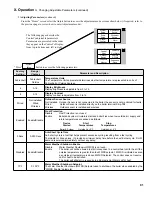
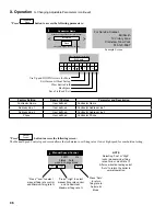
“Press”
Domestic
Hot Water
button to access the following parameters:
Factory
Setting
range /
Choices
Parameter and Description
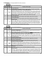
170°F
80°F to
190°F
Domestic Hot Water Setpoint
The Domestic Hot Water (DHW) Setpoint parameter is used to create a minimum boiler water tem
-
perature setpoint that is used when DHW heat demand is “on”.
When the DHW heat demand is not “on” (the contact is open or
not wired
) this setpoint is ignored.
160°F
80°F to
190°F
Domestic Hot Water Thermostat “Sleep” or “away” Setback Setpoint
Thermostat setback setpoint is used when the EnviraCOM thermostat is in “leave” or “sleep” modes
and sensed at E-COM terminals D, R, and C. When setback is “on” the thermostat setback setpoint
shifts the DHW setpoint to lower the DHW temperature and to save energy while home is in a reduced
room temperature mode.
5°F
2°F to 10°F
Domestic Hot Water Diff above
The boiler stops when the water temperature rises ‘Diff Above’ degrees above the setpoint.
7°F
2°F to 30°F
Domestic Hot Water Diff Below
The boiler starts when the water temperature drops ‘Diff Below’ degrees below the setpoint.
Enable
Enable
Disable
Domestic Hot Water Priority (DHWP)
When Domestic Hot Water Priority is Enabled and Domestic Hot Water (DHW) heat demand is “on”
the DHW demand will take “Priority” over home heating demand. When the System and Boiler pumps
are configured as “Central Heat (off DHW priority)” or “Central Heat, Optional Priority” then they will
be forced “off” during DHW Priority. Priority protection time is provided to end DHWP in the event of a
failed or excessive long DHW demand.
60
Minutes
30 to 120
Minutes
Priority Time
When DHWP is Enabled the Priority Time Parameter appears and is adjustable.
3
1 to 5
response Speed
This parameter adjusts the Domestic Hot Water temperature controller Proportion Integral Derivative
(PID) values. Higher values cause a larger firing rate change for each degree of temperature change.
If set too high firing rate “overshoots” required value, increases to high fire causing the temperature
to exceed the “Diff Above” setpoint and cycle the boiler unnecessarily. Lower values cause a smaller
firing rate change for each degree of temperature change. If set too low, the firing rate response will
be sluggish and temperature will wander away from setpoint.
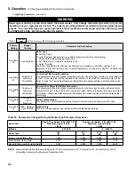
“Press”
Central
Heat
button to access the following parameters:
Factory
Setting
range /
Choices
Parameter and Description
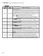
180°F
80°F to
190°F
Central Heat Setpoint
Target temperature for the central heat priority. Value also used by the outdoor air reset function.
170°F
80°F to
190°F
Central Heat Thermostat “Sleep” or “away” Setback Setpoint
Thermostat setback setpoint is used when the EnviraCOM thermostat is in “leave” or “sleep” modes
and sensed at E-COM terminals D, R, and C. When setback is “on” the thermostat setback setpoint
shifts the reset curve to save energy while home is in a reduced room temperature mode. The reset
curve is shifted by the difference between the High Boiler Water Temperature and the Thermostat
Setback Setpoint. Honeywell VisionPro IAQ part number TH9421C1004 is a “setback” EnviraCOM
enabled thermostat. When connected, it allows boiler water setback cost savings.
5°F
2°F to 10°F
Central Heat Diff above
The boiler stops when the water temperature rises ‘Diff Above’ degrees above the setpoint.
7°F
2°F to 30°F
Central Heat Diff Below
The boiler starts when the water temperature drops ‘Diff Below’ degrees below the setpoint.
3
1 to 5
response Speed
This parameter adjusts the Central Heat temperature controller Proportion Integral Derivative (PID)
values. Higher values cause a larger firing rate change for each degree of temperature change. If
set too high firing rate “overshoots” required value, increases to high fire causing the temperature to
exceed the “Diff Above” setpoint and cycle the boiler unnecessarily. Lower values cause a smaller
firing rate change for each degree of temperature change. If set too low, the firing rate response will
be sluggish and temperature will wander away from setpoint.
Summary of Contents for Apex APX399
Page 65: ...65 VIII Electrical continued Figure 43 Ladder Diagram ...
Page 66: ...66 VIII Electrical continued ...
Page 67: ...67 Figure 44 Wiring Connections Diagram VIII Electrical continued ...
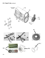
Page 110: ...110 1P 3 1P 2 1P 1 XIII Repair Parts continued 1C 1D 1E ...
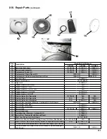
Page 116: ...116 XIII Repair Parts continued ...
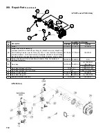
Page 118: ...118 XIII Repair Parts continued ...
Page 129: ...129 SERVICE RECORD DATE SERVICE PERFORMED ...
Page 130: ...130 SERVICE RECORD DATE SERVICE PERFORMED ...

