

62
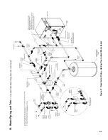
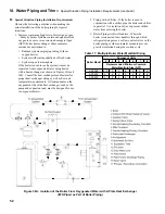
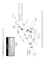
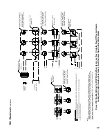
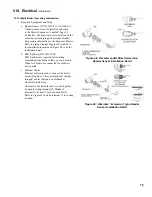
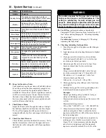
Figure 42: gas inlet Pressure Tap and Pressure Switch Location
Vii. gas Piping
(continued)
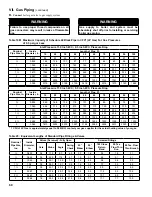
2. For the low and high gas pressure switches proper
operation, the boiler inlet gas pressure must be
within 4.5” w.c. to 13.5” w.c range.
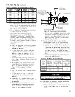
3. The gas pressure can be measured at the gas valve
inlet pressure port. Refer to Figure 42 “Gas Inlet
Pressure Tap and Pressure Switch Location “.
4. If either pressure switch is tripped, it must be
manually reset before the boiler can be restarted.
E.
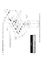
Gas Piping for Multiple Boiler Installation
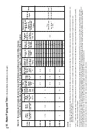
1. Individual module (boiler) gas pipe sizing specific
details - see Paragraph A.
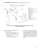
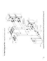
2. Individual module (boiler) recommended gas piping
detail - see Figure 41.
MANUAL
GAS SHUTOFF
VALVE
INLET
TEST
PORT (P1)
OUTLET
TEST
PORT (P2)
SIZE 625 THRU 800
RIGHT SIDE PANEL & BLOWER
OMITTED FOR CLARITY
MANUAL RESET
BUTTON
HIGH PRESSURE
SWITCH
MANUAL RESET
BUTTON
LOW PRESSURE
SWITCH
MANUAL RESET
BUTTON
HIGH PRESSURE
SWITCH
INLET
TEST
PORT (P1)
LOW PRESSURE
SWITCH
SIZE 500 ONLY
LEFT SIDE PANEL & BLOWER
OMITTED FOR CLARITY
6" LONG PIPE NIPPLE
(USED ON 500 ONLY)
3
4
" NPT PIPE PLUG
(USED ON 625 THRU 800)
PART OF FACTORY
INSTALLED GAS TRAIN.
PRESSURE SWITCH
ASSEMBLY
MANUAL RESET
BUTTON
OUTLET
TEST
PORT (P2)
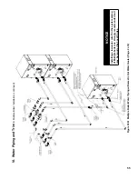
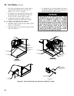
3. An additional gas pressure regulator(s) may need to
be installed to properly regulate inlet gas pressure at
the smallest individual module (boiler).
Warning
if gas pressure in the building is above ½ psig,
an additional gas pressure regulator is required.
Using one additional regulator for multiple
boilers may result in unsafe boiler operation.
The additional regulator must be able to properly
regulate gas pressure at the input of the smallest
boiler. if the regulator cannot do this, two or
more additional regulators are required. Consult
regulator manufacturer and/or local gas supplier
for instructions and equipment ratings.
Summary of Contents for Apex APX399
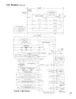
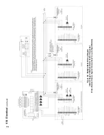
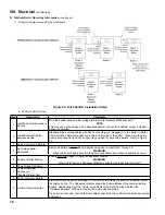
Page 65: ...65 VIII Electrical continued Figure 43 Ladder Diagram ...
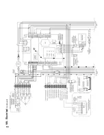
Page 66: ...66 VIII Electrical continued ...
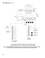
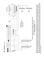
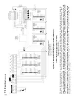
Page 67: ...67 Figure 44 Wiring Connections Diagram VIII Electrical continued ...
Page 110: ...110 1P 3 1P 2 1P 1 XIII Repair Parts continued 1C 1D 1E ...
Page 116: ...116 XIII Repair Parts continued ...
Page 118: ...118 XIII Repair Parts continued ...
Page 129: ...129 SERVICE RECORD DATE SERVICE PERFORMED ...
Page 130: ...130 SERVICE RECORD DATE SERVICE PERFORMED ...