background image

119

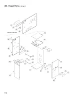
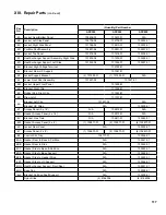
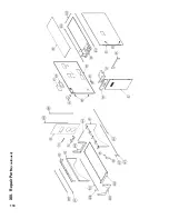
Xiii.  repair Parts

 (continued)

Key 

no. Description

(Quantity) Part number

aPX399

aPX500

aPX800

6A

Jacket, Rear/Bottom Panel

103406-02

103407-01

N/A

6B

Jacket, Left Side Panel

102776-06

102776-07

103232-01

6C

Jacket, Right Side Panel

102776-02

102610-01

103233-01

6D

Partition Shelf Assembly

102831-06

102831-07

103237-01

6E

Jacket, Top Panel

101218-06

101218-07

103234-01

6F

Heat Exchanger Support Assembly, Right Side

101232-06

101232-07

103228-01

6G

Heat Exchanger Support, Left Side

101224-06

101224-07

103227-01

6H

Bracket, High Voltage Terminal

102780-01

6J

Bracket, Rear HX Support

101381-01

6K

Jacket Support Bracket

(2) 101593-01

(1) 101593-01

N/A

6L

Lower Front Door Assembly

101227-02

101227-01

6M

Jacket, Upper Front Panel

101509-01

6N

Bracket, Right Clip

101508-01

6P

Rubber Pad, Right Clip

101245-01

6R

Draw Latch

101037-01

6S

Bracket, Left Clip

101507-02

N/A

Bracket, HX Strap

N/A

103229-01

6T

Access Panel (5’ x 16’)

N/A

102612-01

N/A

6U

Gasket, Access Panel (5’ x 16’)

N/A

102613-01

N/A

6V

Bracket, Gas Train

N/A

102611-01

103240-01

6W

Gasket, Access Panel (5’ x 8’)

(1) 102877-01

(2) 102877-01

(6) 102877-01

6X

Jacket, Rear Panel

N/A

103230-01

6Y

Access Panel (5’ x 8’)

(1) 102873-01

(2) 102873-01

(6) 102873-01

6Z

Control, Slid Tray

102777-01

103336-01

6AA

Gasket, Rear to Base & Partition

N/A

103241-01

6BB

Gasket, Rear to Side

N/A

103242-01

6CC Gasket, Side to Base & Partition

N/A

103243-01

6DD Gasket, Side to Base Support

N/A

103244-01

6EE Gasket, Side to Header Strap

N/A

103245-01

6FF Gasket, Side to HX Support

N/A

103246-01

6GG

Heat Exchanger Support, Front/Rear

N/A

103231-01

6HH Base Pan

N/A

103226-01

6JJ

Bracket, Partition Shelf Support

N/A

103239-01

Nylon Glide

(4) 8186006

(6) 8186006

Summary of Contents for Apex APX399

Page 1: ... of life For assistance or additional information consult a qualified installer service agency or the gas supplier This boiler requires a special venting system Read these instructions carefully before installing INSTALLATION OPERATING AND SERVICE INSTRUCTIONS FOR APEX CONDENSING HIGH EFFICIENCY DIRECT VENT GAS FIRED HOT WATER BOILER 9700609 ...

Page 2: ...e http license reg state ma us pubLic pl_products pb_pre_form asp for the latest Approval Code or ask your local Sales Representative The Commonwealth of Massachusetts requires this product to be installed by a Licensed Plumber or Gas Fitter DANGER Indicates an imminently hazardous situation which if not avoided will result in death serious injury or substantial property damage CAUTION Indicates a...

Page 3: ...ll be permanently mounted to the exterior of the building at a minimum height of eight 8 feet above grade directly in line with the exhaust vent terminal for the horizontally vented gas fueled heating appliance or equipment The sign shall read in print size no less than one half 1 2 inch in size GAS VENT DIRECTLY BELOW KEEP CLEAR OF ALL OBSTRUCTIONS 4 A final inspection by the state or local gas i...

Page 4: ...e installed on the heating system to prevent damage if the boiler is inoperative This boiler contains very hot water under high pressure Do not unscrew any pipe fittings nor attempt to disconnect any components of this boiler without positively assuring the water is cool and has no pressure Always wear protective clothing and equipment when installing starting up or servicing this boiler to preven...

Page 5: ...Trim 45 VII Gas Piping 59 VIII Electrical 63 IX System Start Up 75 X Operation 81 A Overview 81 B Supply Water Temperature Regulation 82 C Boiler Protection Features 83 D Multiple Boiler Control Sequencer 84 E Boiler Sequence of Operation 85 1 Normal Operation 85 2 Using the Display 86 F Viewing Boiler Status 87 1 Status Screens 87 2 DetailScreens 88 3 Multiple Boiler Sequencer Screens 89 G Changi...

Page 6: ...t designed for use in gravity hot water space heating systems or systems containing significant amount of dissolved oxygen swimming pool water heating direct domestic hot water heating etc Table 1 Dimensional Data See Figures 1A 1B and 1C Dimension Boiler Model APX399 APX500 APX800 A Inch mm 28 7 8 734 44 7 8 1140 54 9 16 1384 B Inch mm 6 3 16 157 22 1 8 562 28 3 8 724 C Inch mm 13 1 16 332 29 737...

Page 7: ...7 I Product Description Specifications and Dimensional Data continued Figure 1A Apex Model APX399 ...

Page 8: ...8 Figure 1B Apex Model APX500 I Product Description Specifications and Dimensional Data continued ...

Page 9: ...9 I Product Description Specifications and Dimensional Data continued Figure 1C Apex Model APX800 ...

Page 10: ... for each 1000 Feet above sea level Apex Series Gas Fired Boilers Model Number Input MBH Output MBH Net AHRI Ratings Water MBH Thermal Efficiency Combustion Efficiency Boiler Water Volume Gal Heat Transfer Area Sq Ft Min Max APX399 80 399 375 328 94 1 94 5 3 4 41 8 APX500 167 500 475 413 95 0 95 0 4 2 50 8 APX800 267 800 760 661 95 0 93 0 5 0 65 3 Notes Gross Output Maximum Allowable Working Press...

Page 11: ...Z223 1 Air for Combustion and Ventilation Canada Natural Gas and Propane Installation Code CAN CSA B149 1 Venting Systems and Air Supply for Appliances III Pre Installation and Boiler Mounting WARNING Adequate combustion and ventilation air must be provided to assure proper combustion F The boiler should be located so as to minimize the length of the vent system The PVC combustion air piping or th...

Page 12: ...o the Combustible Material Clearances provided 1 The boiler front is accessible thru a door 2 Access is provided to the condensate trap located on the left side of boiler 3 Access is provided to thermal link located at the boiler rear Approved Direct Vent System Vent Pipe Material Vent Pipe Direction Enclosure Vent Pipe Nominal Diameter Minimum Clearance to Combustible Material Factory Standard Tw...

Page 13: ... must align with a matching bottom boiler left side panel top positioning dimple Once bracket holes and side panel dimple alignment is verified attach the bracket to top and bottom boiler left side panels with the mounting screws e Repeat above procedure to install second Stacking Boiler Attachment Bracket and secure the stacked boiler right side panels together at the front right corner f Install...

Page 14: ... combination c Water Piping and Trim Follow instructions in Section VI Water Piping and Trim of the manual for system piping and boiler secondary piping selection sizing based on combined heating capacity and or gross output of the selected stackable boiler combination Follow instructions of Section VI Water Piping and Trim for each individual boiler trim installation d Electrical Follow instructi...

Page 15: ...slope down towards terminal when possible If not slope toward boiler 6 Do not install venting system components on the exterior of the building except as specifically required by these instructions refer to Figure 4 a Vent terminals must be at least 1 foot from door window or gravity inlet into the building b Maintain the correct clearance and orientation between the vent and air intake terminals ...

Page 16: ...ewall The system includes separate stainless steel vent pipe and PVC galvanized steel air intake pipe terminating thru sidewall with individual penetrations for the vent and air intake piping and separate terminals 9A 9B 16 17 11A 11B D Optional Snorkel thru sidewall Same as above but separate snorkel type terminals 11 16 17 Vertical Vertical thru roof The system includes separate stainless steel ...

Page 17: ... Vent Terminal Relative to Windows Doors Grades Overhangs Meters and Forced Air Inlets Concentric Terminal Shown Two Pipe System Vent Terminal to be installed in same location Two Pipe System Air Intake Terminal Not Shown IV Venting A General Guidelines continued wind Reliable operation of this boiler cannot be guaranteed if the terminal is subjected to winds in excess of 40 mph o Air intake termi...

Page 18: ... where air cannot circulate freely such as air inside a stud wall and in any boiler closet or chase way When using the CPVC PVC vent options the useofCPVCisrequiredwhenventinginvertical or horizontal chase ways All condensate that forms in the vent must be able to drain back to the boiler 1 Components and Length Restrictions a See Table 5A for CPVC PVC Vent Air Intake Components included with boil...

Page 19: ...o boiler rear bottom panel and insert vent connector inner stainless steel vent pipe into heat exchanger vent outlet b Align vent connector plate and gasket clearance holes with rear bottom panel engagement holes than secure the connector and gasket to the panel with six mounting screws c Apply supplied dielectric grease grease pouch attached to two pipe vent connector to gasket inside vent sectio...

Page 20: ...4 Sch 40 PVC Pipe x 5 Ft Long 5 IV Venting B CPVC PVC Venting continued Figure 5 Expansion Loop and Offset 2 L 5 6 MIN 6 MIN 5 4 4 2 LONG RUN OF PIPE CHANGE OF DIRECTION VERTICAL OR HORIZONTAL LOOP HORIZONTAL ONLY TOP VIEW OFFSET L L L L LOOP LENGTH L L L RESTRAINT RESTRICTS MOVEMENT HANGER ALLOWS MOVEMENT KEY Nominal Pipe Dia In Length of Straight Run Ft Loop Length L In 4 20 60 30 74 40 85 50 95...

Page 21: ...rap c All CPVC vent components supplied with boiler inside vent carton 4 Schedule 40 x 30 Figure 7 Near Boiler Vent Combustion Air Piping long CPVC pipe and 4 Schedule 80 CPVC 90 Elbow must be used for near boiler piping before transitioning to Schedule 40 PVC ASTM 2665 pipe components for reminder of vent system The CPVC 30 long straight pipe may be cut to accommodate desired vent configuration p...

Page 22: ... PVC Installer Supplied Nominal Diameter In Quantity Length Ft Equivalent Length Ft Ft Subtotal Equivalent Ft C Nominal Diameter In Quantity Length Ft Equivalent Length Ft Ft Subtotal Equivalent Ft B 4 1 4 4 5 6 1 6 7 5 Total Equivalent Length Ft A B C 30 2 5 Ft Straight Pipe CPVC Supplied with Boiler Nominal Diameter In Quantity Length Ft Equivalent Length Ft Ft Subtotal Equivalent Ft E 4 2 5 1 2...

Page 23: ...e first elbow used in the vent system as it exits the boiler j Apply a coating of the sealant at least 1 wide onto 6 Schedule 40 PVC combustion air pipe installer provided k Insert the coated end of the PVC pipe with a slight twisting motion into the connector air intake section and secure by tightening the metal strap l Clean all vent and combustion air pipe joints with primer and secure with tra...

Page 24: ...ure 10 for appropriate configuration details Figure 10 Rodent Screen Installation IV Venting B CPVC PVC Venting continued Figure 9B Direct Vent Sidewall Terminations Optional WARNING All CPVC pipe supplied with boiler vent carton must be used as part of vent system prior to connecting supplied PVC vent terminal Methods of securing and sealing terminals to the outside wall must not restrain the the...

Page 25: ...walls The fire stop must close the opening between the vent pipe and the structure Whenever possible install vent straight through the roof Refer to Figures 12 and 13 Sizeroofopeningtomaintainminimum clearance of 1 from combustible materials Extend vent pipe to maintain minimum vertical and horizontal distance of twelve 12 inches from roof surface Additionalverticaldistanceforexpected snow accumul...

Page 26: ... approved for use with polypropylene vent system It is an installing contractor responsibility to procure listed below polypropylene vent system pipe and related components Polypropylene vent system manufactures are listed below Approved Polypropylene Vent System Manufacturers Make Model M G DuraVent PolyPro Single Wall Rigid Vent PolyPro Flex Flexible Vent APX399 and APX500 Centrotherm Eco System...

Page 27: ...nstructionsandApexboilerInstallation Operating and Service Instructions the more restrictive instructions shall govern Apex Boiler Two Pipe Vent System Connector Field Modification Procedure To Accept Polypropylene Vent Piping Apex boilers are factory supplied with a model specific boiler two pipe CPVC PVC vent system connector shipped within a model specific boiler CPVC gasketed vent kit carton L...

Page 28: ...rovided dielectric grease grease pouch taped to the vent system connector all around to the vent or air connection inner red silicon gasket 10 APX399 and APX500 models Push and twist PVC to PP boiler adapter ISAA0404 or ISAAL0404 into two pipe vent system connector vent connection or air supply port until bottomed out 11 Tighten the worm band clamp screw to secure PVC to PP boiler adapter 12 Do no...

Page 29: ...s for possible shipping damage prior to installation Proper joint assembly is essential for safe installation The venting system must be free to expand and contract and supported in accordance with installation instructions included by the original polypropylene venting component manufacturers M G DuraVent or Centrotherm whichever applicable Do not mix vent components or joining methods for differ...

Page 30: ... the stainless steel vent adapter P N 102220 01 4 a Push the stainless steel vent adapter onto the CPVC PVC connector with a slight twisting motion Make sure that the stainless steel vent adapter is inserted at least 1 refer to Figure 16 b Secure the adapter to the CPVC PVC connector by tightening the metal strap To install the stainless steel vent adapter P N 103285 01 6 c Apply a coating of supp...

Page 31: ...nt System Adapter for Stainless Steel Apply a heavy bead of silicone to the male end of the terminal before inserting it into the last piece of pipe Orient the terminal so that the seam in the terminal is at 12 00 Smooth the silicone over the seam between the terminal and the last piece of pipe applying additional silicone if necessary to ensure a tight seal Allow the silicone to cure per the sili...

Page 32: ...cellaneous Parts Carton b Position the Collar onto jacket combination rear bottom panel and insert collar inner stainless steel vent pipe into the heat exchanger vent outlet IV Venting D Stainless Steel Venting continued Table 12 Concentric Vent Length Boiler Model Inner Outer Pipe Dia mm Vent Length Equiv Ft Wall Opening Diameter Minimum Maximum APX399 100 150 mm 32 in 60 6 1 2 in APX500 100 150 ...

Page 33: ... cut the Concentric Vent Straight pipe to required length refer to Figure 20 Cutting Straight Pipe and the following procedure i Determine the required length of the outer pipe When doing this allow an additional 1 of length for insertion into the female end of the adjoining pipe Mark the cut line on the outer pipe ii Remove the plastic inner pipe by pulling it out from the female end iii Cut the ...

Page 34: ...tion mark made in Step 4 above is covered On other fittings the bead on the male pipe will be bottom out on the collar see Figure 22 iii The male end of cuttable fittings must be held to the collar with three 3 10 x 1 2 sheet metal screws Drill a 1 8 hole through both outer pipes to start this screw Use a drill stop or other means to ensure that the drill bit does not penetrate more than 3 8 into ...

Page 35: ...orizontal Wall Terminal Cut a 6 for 100 150 mm at the planned location of the horizontal terminal Measure dimension L from exterior wall outer surface to the end of the last fitting See Figure 24 Dimension L Figure 23 Horizontal Concentric Venting IV Venting E Concentric Polypropylene Venting continued Figure 24 Dimension L When factory Horizontal Wall Terminal needs to be shortened measure dimens...

Page 36: ...round then push the termination male end inside boiler concentric vent collar or the last section of the vent pipe until the mark see Step v is no longer visible Re install locking band clamp onto the joint to secure the terminal to the collar or the last section of the vent pipe 5 Vertical Vent Termination a Standard Concentric Termination Refer to Figures 27 thru 31 i In addition to the vertical...

Page 37: ...37 IV Venting E Concentric Polypropylene Venting continued Figure 26 Completing Horizontal Wall Terminal Installation Figure 27 Vertical Concentric Vent Installation Figure 28 Dimension H ...

Page 38: ...isible Secure the terminal to the last piece of pipe with three 10 x 1 2 sheet metal screws Drill a 1 8 hole through both outer pipes to start these screws Use a drill stop or other means to ensure that the drill bit does not penetrate more than 3 8 into the outer pipe Do not use a sheet metal screw longer than 1 2 Secure the terminal section to the inside of the roof structure using the mounting ...

Page 39: ...ers and any appliance not connected to the common venting system Turn on any exhaust fans such as range hoods and bathroom exhausts so they will operate at maxi mum speed Do not operate a summer exhaust fan Close fireplace dampers 4 Place in operation the appliance being inspected Follow the Lighting or Operating Instructions Adjust thermo stat so appliance will operate continuously 5 Test for spi...

Page 40: ... boiler combustion air intake guidelines and options IV Venting G Multiple Boiler Installation Venting continued c The individual module boiler maximum combustion air intake pipe length see Table 8 d If possible locate each individual module boiler both combustion air intake termination and vent termination on the same sidewall to prevent nuisance boiler shutdowns However if same sidewall placemen...

Page 41: ...41 Figure 32 Multiple Boiler Direct Vent Termination IV Venting G Multiple Boiler Installation Venting continued ...

Page 42: ...42 Figure 33 Multiple Boiler Concentric Vent Termination IV Venting G Multiple Boiler Installation Venting continued ...

Page 43: ...pipe connections Refer to Figures 1A and 1B IV Venting G Multiple Boiler Installation Venting continued If vertical vent terminals cannot end in one plane they must be spaced no closer then three 3 feet horizontally h When individual modules boilers are installed in the same horizontal plane chimney chase vertical concentric venting is permitted provided i Sufficient inside space available at the ...

Page 44: ...etween limestone and acidic condensate and lose neutralizing V Condensate Disposal continued effectiveness over time Therefore periodic condensate neutralizer maintenance and limestone chip replacement must be performed A pH test or acid test kits are available from HVAC plumbing distributors and should be used to measure condensate acidity before after neutralizer thus indicating a need for servi...

Page 45: ...during appliance operation and service circulator replacement etc Oxygen contamination of boiler water will cause corrosion of iron and steel boiler components and can lead to boiler failure Burnham Commercial s Standard Warranty does not cover problems caused by oxygen contamination of boiler water or scale lime build up caused by frequent addition of water Do not fill boiler with softened water ...

Page 46: ...ing 2 NPT x 2 1 2 long black nipple 2 x 2 x NPT black tee x NPT black reducing bushing and Temperature Pressure Gauge g Mount 2 NPT coupling onto 2 MPT boiler supply stub see Figure 1C then install 2 NPT x 2 1 2 long black nipple into the coupling VI Water Piping and Trim A Factory Supplied Piping and Trim continued Boiler Model Boiler Supply Connection Inch FPT Boiler Return Connection Inch FPT M...

Page 47: ...g via closely spaced tees to insure specified flow range through boiler any time the boiler is firing a The flow rate through the isolated near boiler loop is maintained by factory recommended and installer supplied boiler circulator b The flow rate through the isolated near boiler loop is completely independent of the flow rate through the heating system loop s c The flow rate through the heating...

Page 48: ...ing an existing boiler with no other changes in the system the old expansion tank can generally be reused If the expansion tank must be replaced consult the expansion tank manufacturer s literature for proper sizing 4 Fill Valve Required Either manual recommended or automatic fill valve may be used However if automatic refill is employed a water meter must be added to evaluate the makeup water vol...

Page 49: ...d water and settles over the warmest surfaces of boiler heat exchanger causing subsequent overheating and eventual failure Water hardness must be maintained within 3 to 9 grain gal range RefertoSectionXI ServiceandMaintenance forrecommendedheatingsystemwatertreatmentproducts corrosion scale inhibitors cleaners etc and their suppliers VI Water Piping and Trim C Standard Installation Requirements co...

Page 50: ...50 Figure 36 Near Boiler Piping Heating Only VI Water Piping and Trim C Standard Installation Requirements continued ...

Page 51: ...51 Figure 37 Near Boiler Piping Heating Plus Indirect Water Heater VI Water Piping and Trim C Standard Installation Requirements continued ...

Page 52: ...ll components on the oxygenated side of the heat exchanger such as the pump and expansion tank must be designed for use in oxygenated water Table 17 Multiple Boiler Water Manifold Sizing Boiler Model Number of Units 2 3 4 5 6 7 8 Recommended Minimum Common Water Manifold Size NPT APX399 2 3 3 4 5 5 5 APX500 3 4 4 5 5 6 6 APX800 3 5 5 6 6 8 8 VI Water Piping and Trim D Special Situation Piping Inst...

Page 53: ...arding an individual module boiler piping system specific details c Selection criteria for individual module boiler space heating and or DHW circulators 2 For installations where indirect domestic hot water heater is combined with space heating the Alliance SL model must be piped as a separate heating zone off the system header The circulator must be sized based on the Alliance SL model coil flow ...

Page 54: ...estic Hot Water Heater Page 1 of 2 VI Water Piping and Trim E Multiple Boiler Installation Water Piping continued NOTICE Installing a low water cutoff in the system piping of Multiple boilers is strongly recommended and may be required by Local Codes ...

Page 55: ... w Domestic Hot Water Heater Page 2 of 2 VI Water Piping and Trim E Multiple Boiler Installation continued NOTICE Installing a low water cutoff in the system piping of Multiple boilers is strongly recommended and may be required by Local Codes ...

Page 56: ...UTION It is the installers responsibility to select pumps and boiler piping configurations that provide the proper flow rates and performance for the boiler and indirect water heater Refer to Table 15 for recommended Boiler Loop Circulator VI Water Piping and Trim E Multiple Boiler Installation continued ...

Page 57: ...57 Figure 40B Alternate Multiple Boiler Water Piping w Indirect Domestic Hot Water Heater Page 2 of 2 VI Water Piping and Trim E Multiple Boiler Installation continued ...

Page 58: ...arate heating zone off system header see Figure 39A and 39B for IWH piping Indirect Water Heater Circulator must be selected by an installer based on Alliance SL required coil flow and corresponding coil head loss shown as well as total equivalent length of such separate zone Note 2 The IWH may be installed as part of Boiler piping when boiler DHW modulation rate input is adjusted to closely match...

Page 59: ...pe Size In Inside Diameter In Length of Pipe Ft 10 20 30 40 50 60 70 80 90 100 0 622 172 118 95 81 72 65 60 56 52 50 0 824 360 247 199 170 151 137 126 117 110 104 1 1 049 678 466 374 320 284 257 237 220 207 195 1 1 380 1392 957 768 657 583 528 486 452 424 400 1 1 610 2085 1433 1151 985 873 791 728 677 635 600 2 2 067 4016 2760 2217 1897 1681 1523 1402 1304 1223 1156 2 2 469 6401 4400 3533 3024 268...

Page 60: ... 067 2703 1858 1492 1277 1131 1025 943 877 823 778 2 2 469 4308 2961 2377 2035 1803 1634 1503 1399 1312 1239 3 3 068 7615 5234 4203 3597 3188 2889 2658 2472 2320 2191 1 CFH of LP Gas is approximately equal to 2 5 MBH contact your gas supplier for the actual heating value of your gas Table 20 Equivalent Lengths of Standard Pipe Fittings Valves Nominal Pipe Size Inc Inside Diameter In Valves Screwed...

Page 61: ... components prior to connecting boiler to gas supply system piping as follows APX500 a Locate and remove the NPT x 6 long black nipple and NPT external gas shutoff valve required for APX500 b APX500 boiler has NPT x 12 long black nipple and left side panel grommet factory installed disregard the supplied NPT x 6 long black nipple in the Miscellaneous Part Carton c Mount the NPT external gas shutof...

Page 62: ...TTON HIGH PRESSURE SWITCH MANUAL RESET BUTTON LOW PRESSURE SWITCH MANUAL RESET BUTTON HIGH PRESSURE SWITCH INLET TEST PORT P1 LOW PRESSURE SWITCH SIZE 500 ONLY LEFT SIDE PANEL BLOWER OMITTED FOR CLARITY 6 LONG PIPE NIPPLE USED ON 500 ONLY 3 4 NPT PIPE PLUG USED ON 625 THRU 800 PART OF FACTORY INSTALLED GAS TRAIN PRESSURE SWITCH ASSEMBLY MANUAL RESET BUTTON OUTLET TEST PORT P2 3 An additional gas p...

Page 63: ...reen Ground connection DANGER Positively assure all electrical connections are unpowered before attempting installation or service of electrical components or connections of the boiler or building Lock out all electrical boxes with padlock once power is turned off WARNING Failure to properly wire electrical connections to the boiler may result in serious physical harm Electrical power may be from ...

Page 64: ...f the shielding on this cable to ground WARNING When making low voltage connections make sure that no external power source is present in the thermostat or limit circuits If such a power source is present it could destroy the boiler s Microprocessor Control Sage2 1 One example of an external power source that could be inadvertently connected to the low voltage connections is a transformer in old t...

Page 65: ...65 VIII Electrical continued Figure 43 Ladder Diagram ...

Page 66: ...66 VIII Electrical continued ...

Page 67: ...67 Figure 44 Wiring Connections Diagram VIII Electrical continued ...

Page 68: ...ure 45A Modified Wiring For DHW Priority When Using Low Flow Circulator Piped Off System Header Heating with Central Heating Circulators Plus Alternately Piped Indirect Water Heater VIII Electrical continued ...

Page 69: ...T POWER SUPPLY 120 60 1 FIELD INSTALLED 40VA TRANSFORMER SEE NOTE 2 WIRE 24V THERMOSTATS W HEAT ANTICIPATOR SET AT 0 9 AMPS 40VA REQ D FOR EVERY 3 ZONE VALVES 2 WIRE 24V THERMOSTATS W HEAT ANTICIPATOR SET AT 0 5 AMPS 40VA REQ D FOR EVERY 4 ZONE VALVES 2 WIRE 24V THERMOSTATS W HEAT ANTICIPATOR SET AT 0 3 AMPS 40VA REQ D FOR EVERY 4 ZONE VALVES WHITE ROGERS 1361 102 ZONE VALVES CHECK FOR CROSS PHASI...

Page 70: ...70 Figure 46 Multiple Boiler Wiring Diagram Internal Sage2 1 Multiple Boiler Control Sequencer Three Boilers Shown Typical Connections for up to Eight Boilers VIII Electrical continued ...

Page 71: ... the Tekmar 265 Control and each boiler s Sage2 1 Control The boiler s and system supply water temperature will be reset together to maintain the input that is needed to the system When a call for Indirect Hot Water is generated to the Tekmar 265 the control will de energize the zone pump control ZC terminal energize the Indirect pump and modulate the boiler firing to establish a setpoint temperat...

Page 72: ... temperature to supply enough input to the system main to satisfy the desired reset water temperature in the main established by the Tekmar 264 Control When a call for Indirect Hot Water is generated to the Tekmar 264 the control will de energize the zone pump control ZC terminal energize the Indirect pump and sequentially fire the boilers to establish a setpoint temperature in the main for the In...

Page 73: ...192 01 RJ45 Splitters are required for installing communications between three or more boilers When two boilers are connected the splitter is not required c Ethernet Cables Ethernet cables are used to connect the boiler network together These are standard straight through cables that can be purchased at electrical distributors Alternately the network can be wired together by simply wiring terminal...

Page 74: ...ique Boiler Address using any number from 1 through 8 WARNING When two boiler s addresses are the same undesirable simultaneous operation occurs 5 Enable 1 Boiler Master Enable only one Sage2 1 Control s Sequencer Master WARNING When more than one Sequencer Master is enable erratic behavior will result 6 Power Down All Boilers 7 Power Up Master Sequencer Enabled Boiler First 8 Power Up Other Boile...

Page 75: ...gas supplier 2 Apex gas valves have inlet and outlet pressure taps with built in shut off screw Turn each screw from fully closed position three to four turns counterclockwise to open taps Connect manometers to pressure taps on gas valve NOTICE If it is required to perform a long term pressure test of the hydronic system the boiler should first be isolated to avoid a pressure loss due to the escap...

Page 76: ...76 IX System Start up continued Apex Series Lighting and Operating Instructions Figure 51 Lighting Instructions ...

Page 77: ... 72 Seconds for 2 Revolutions i e 36 seconds per 1 cubic foot Calculate hourly gas flow rate 3600 sec hr 36 sec cu ft 100 cu ft hr 5 Obtain gas heating value Btu per cubic foot from gas supplier 6 Multiply hourly gas flow rate by gas heating value to determine the boiler input rate BTU hr Example Natural gas heating value provided by local gas utility is 1050 Btu per cubic foot Measured and calcul...

Page 78: ...unterclockwise see Figure 53 in turn increments and checking the rate after every adjustment until the measured input rate value falls within 88 to 100 of the value listed on the boiler rating label If a boiler is equipped with two gas valves throttle screw adjustments must be done to both gas valves equally and simultaneously 10 To lock the boiler in low fire select Low from manual control screen...

Page 79: ...RNING This conversion should be performed by a qualified service agency in accordance with the manufacturer s instructions and all applicable codes and requirements of the authority having jurisdiction If the information in these instructions is not followed exactly a fire an explosion or production of carbon monoxide may result causing property damage personal injury or loss of life The qualified...

Page 80: ...titude Range 0 5000 Ft 5001 10000 Ft CO2 O2 Range CO PPM APX399 11 4 9 5 High Fire 11 4 9 1 Low Fire 3 5 6 5 High Fire 3 5 7 0 Low Fire Less than 100 PPM APX500 APX800 10 8 9 1 High Fire 10 8 9 1 Low Fire 4 5 7 0 High Fire 4 5 7 0 Low Fire Table 26 Typical Combustion Settings LP Gas WARNING These instructions include a procedure for adjusting the air fuel mixture on this boiler This procedure requ...

Page 81: ...ncreases 6 Warm Weather Shutdown WWSD Some boilers are used primarily for heating buildings and the boilers can be automatically shutdown when the outdoor air temperature is warm When outside air temperature is above the WWSD setpoint this function will shut down the boiler boiler pump and or the system pump 7 Domestic Hot Water Priority DHWP Someboilersareusedprimarilyforbuildingspaceheating but ...

Page 82: ...automatically adjust downwards as the outdoor temperature increases When the water temperature is properlymatchedtoheatingneedsthereisminimalchance of room air temperature overshoot Excessive heat is not sent to the room heating elements by overheated supplywatertemperaturemaintainedtoohighasetting water Reset control saves energy by reducing room over heating reducing boiler temperature increasin...

Page 83: ...wn the boiler and delays restart If the inverted temperature is detected more than five times the boiler manual reset Hard Lockout is set This condition is the result of incorrectly attaching the supply and return piping 5 External Limit An external limit control can be installed between terminals 11 and 12 on the low voltage terminal strip Be sure to remove the jumper when adding an external limi...

Page 84: ...or the remainder of the year 6 Multiple Demands The Sequence Master responds to Central Heat DHW and frost protection demands similar to the stand alone boiler For example when selected and DHW priority is active the sequence master uses DHW setpoint Diff Above Diff Below and pump settings 7 Shared or Isolated DHW Demand When the Indirect Water Heater IWH parameter is set to Primary Piped the Sequ...

Page 85: ... conducted Pre ignition Spark is energized and it is confirmed that no flame is present Direct Ignition Spark and Main fuel valve are energized Supply 132 F 140 F Rate 100 Status Setpoint Boiler 1 Priority Central Heat i Running Priority Central Heat Status Running burner On circulator s On After flame is proven normal boiler operation begins Modulation rate depending on temperature and setpoint s...

Page 86: ...ontrols Contact Your Qualified Heating Professional Improper settings or service create risk of property damage injury or death Service Contact Adjust Lockout History Service Contract Boiler Size Setup Sequencer Setup Active Faults i Supply 180 F 180 F Rate 0 Status Standby Setpoint Boiler 1 Priority Central Heat i Active Fault 180 F Boiler 1 Energy Save On Max Efficiency On Standby i Status Help ...

Page 87: ...trend may indicate pump speed settings need to be changed Cycles and Hours Boiler cycles and hours are used to monitor the boilers overall compatibility to the heating load Excessive cycling compared to run time hours may be an indication of pumping boiler sizing or adjustment issues Priority The selected Priority is shown Available Priorities are Standby no call for heat is present Sequencer Cont...

Page 88: ... Screens Detail screens are accessed by selected the Detail button from the Home screen and provide in depth operating parameter status such as On Point Off Point and Setpoint Source information Demand detail screens are provided for Central Heat shown DHW and Sequencer demands OutdoorResetsavesenergyandimproveshomecomfort by adjusting boiler water temperature This screen presents the active reset...

Page 89: ... for boiler address 1 is provided as follows 1 Boiler 1 is connected to the network 1 Blinking underline boiler 1 is starting 1 Solid underline boiler 1 is running Networked Boilers Boiler 1 Lead 50 Firing Boiler 2 50 Firing Boiler 3 0 Available Boiler 4 0 Available i The Networked Boilers screen is selected by pressing the Detail button from the Home screens and pressing Networked Boilers from th...

Page 90: ...er Password required Installer Password 76 Warning Only Qualified Technicians Should Adjust Controls Contact Your Qualified Heating Professional i Press 5 digit display to Input Password Press Save to enter password i 000 1 CL R ES C 5 4 3 2 6 B S 0 9 8 7 Press 5 digit display to Input Password i 076 After inputting the password press to enter password After password is Saved These buttons access ...

Page 91: ...sor is not monitored for faults Wired Outdoor Sensor is installed directly on the boiler terminal Strip TB2 Wireless Outdoor sensor is installed and wireless Enabled Enable Disable Frost Protection Disable Frost Protection is not used Enable Boiler and system circulators start and boiler fires when low outside air supply and return temperatures are sensed as follows 0 Secs 0 900 Secs Anti Short Cy...

Page 92: ...ated input of the installed home radiation is less than the maximum output of the boiler change the Central Heat Maximum Modulation fan speed setting to limit the boiler output accordingly See Table 30 Minimum to Maximum Modulation Domestic Hot Water DHW Max Modulation This parameter defines the highest modulation rate the Control will go to during a Domestic Hot Water call for heat If the rated i...

Page 93: ...Pump Runs during any call for heat Central heat off DHW demand Pump Runs during central heat and frost protection call for heat Pump does not start for a DHW call for heat and will be forced off if there is a DHW call for heat and Domestic Hot Water Priority is active Primary Loop Pipe IWH Never Primary Loop Piped IWH Boiler Piped IWH Domestic Pump run pump for Activates the Domestic pump output a...

Page 94: ...er 2 Wiring locations Thermostat X DHW call for heat X System pump X DHW pump X Boiler Pump X X Sequencer Master Parameter Selections Sequencer Master Enabled Indirect Water Heater Boiler Piped Pump Parameter Selections System Pump Central Heat No Priority Never Boiler Pump Central Heat Off DHW Priority Any demand DHW Pump Boiler Piped IWH Never Explanation This piping arrangement does not allow b...

Page 95: ...ter call for heat Domestic hot water priority is optional It is permissible for the domestic and system pumps to run at the same time The boiler pump must run for every call for heat Example Pump Parameter selections continued Multiple Boilers IWH piped to primary system pump required to run for any call for heat Sequencer Master Boiler 1 Boiler 2 Wiring locations Thermostat X DHW call for heat X ...

Page 96: ...High Auto Low nOTE Selecting Low or High locks manual mode firing rate at min or max Rate After combustion testing select Auto to return the boiler to normal operation Press Auto to return firing rate to Automatic Mode Press Low to select manual firing rate control and Minimum firing rate Manual Speed Control i Press High to select manual firing rate control and Central Heat Maximum firing rate Us...

Page 97: ... each degree of temperature change If set too high firing rate overshoots required value increases to high fire causing the temperature to exceed the Diff Above setpoint and cycle the boiler unnecessarily Lower values cause a smaller firing rate change for each degree of temperature change If set too low the firing rate response will be sluggish and temperature will wander away from setpoint Press...

Page 98: ...ed in the heat loss calculation It is typically set to the coldest outdoor temperature 70 F 32 F to 100 F High Outdoor Temperature The High Outdoor Temperature parameter is the outdoor temperature at which the Low Boiler Water Temperature is supplied This parameter is typically set to the desired building temperature 110 F 70 F to 190 F Low Boiler Water Temperature The Low Boiler Water Temperature...

Page 99: ...45 40 20 25 30 35 55 60 65 70 15 50 145 115 150 120 140 135 130 125 155 190 160 195 165 185 180 175 170 200 Boost Maximum Off Point Central Heat Setpoint minus Diff Above Low Boiler Water Temp Default 110 F High Outside Air Temp Default 70 F 10 F Hot Water Setpoint Minimum Water Temperature Default 130 F TOD Setback Setpoint Default 170 F Central Heat Setpoint Low Outside Air Temp 180 F 0 F Defaul...

Page 100: ...o DHW Service Primary Piped The Sequence Master responds to the DHW Call For Heat This allows one or more boilers to provide heat to the IWH Disabled Enable Disable DHW Two Boiler Start The Sequencer to immediately start two boilers for a DHW call for heat Used when DHW is the largest demand Only visible when primary piped IWH is selected 120 Secs 120 1200 Secs Boiler Start Delay Slave boiler time...

Page 101: ...its end The yellow light should come on and Limit Open will flash in the Active Faults screen on the display Push the reset button to restore normal operation If yellow light does not come on determine why the low water cutoff is not working properly 2 Follow the procedure for turning the boiler off per Figure 51 Lighting Instructions 3 Inspect the wiring to verify the conductors are in good condi...

Page 102: ...tector Alphi 11 CH Copal sludge remover corrosion inhibitor Follow manufacturer application procedure for proper heating system boiler cleaning and preventive treatment Above referenced products are available from Cookson Electronics Company 4100 Sixth Avenue Altoona PA 16602 Tel 814 946 1611 and or selected HVAC distributors Contact Burnham Commercial for specific details iii Equivalent system wa...

Page 103: ...w the steps below For parts identification refer to Section XIII Repair Parts 1 Condensate Overflow Switch Removal and Replacement a Disconnect power supply to boiler b Remove two 2 wire nuts and disconnect overflow switch wire pigtails from boiler wiring c Using pliers release spring clip securing the overflowswitchtocondensatetrapbodyandremove theswitch Notethattheswitchhasfactoryapplied silicon...

Page 104: ...86 e Using pliers release spring clip securing the overflowswitchtocondensatetrapbodyandremove theswitch Notethattheswitchhasfactoryapplied siliconadhesiveseal whichmayhavetobecarefully cut all around to facilitate the switch removal f Usingpliers releasespringclipsecuringcondensate trap body to the heat exchanger bottom drain stab g Firstly pull the trap downwards to release from the heat exchang...

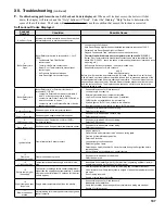
Page 105: ... cause B Display Faults Boiler Energy Save On Max Efficiency On Standby i Status Help Adjust Detail Lockout History Service Contract Boiler Size Setup Sequencer Setup active Faults i 00FF Communication Fault i Limit String Status Rate Limit Status Reset Sensor Status Soft Lockout Hold Hard Lockout 024 F Sensor Fault Help Screen Active Fault Screen Home Screen Figure 60 Help Menu Indication Conditi...

Page 106: ...or closed graphically represents each safety limit The closed contact icon is steady the open contact icon is blinking For example the screen shown to the left illustrates a closed Air Pressure Switch contact and an open Auto Reset High Limit contact The Auto Reset High Limit is causing the boiler to stop firing NOTE Since the limit string items are wired in series all limits downstream of the ope...

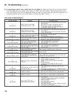
Page 107: ...open See possible causes for Hard Lockout 4 Loose wiring to limit device External Limit defective or jumper not installed Low Gas Pressure Switch contact open if installed LWCO switch not installed and jumper missing If yellow light on LWCO is on system is low on water If neither yellow or green light is on check LWCO harness 7 Return sensor fault Shorted or open return temperature sensor Shorted ...

Page 108: ...s Defective blower 19 Purge rate proving failed Blower is not running at Purge rate when it should or blower speed signal not being detected by Sage2 1 Loose connection in 120 VAC blower wiring Loose or miswired blower speed harness Defective blower 20 Invalid Safety Parameters Unacceptable Sage2 1 control Safety related parameter detected Safety Parameter verification required Contact factory 21 ...

Page 109: ...holesale distributor Should you require assistance in locating a Burnham Commercial Cast Iron distributor in your area or have questions regarding the availability of Burnham Commercial Cast Iron products or repair parts please contact Burnham Commercial Cast Iron Customer Service at 888 791 3790 or Fax 877 501 5211 ...

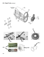
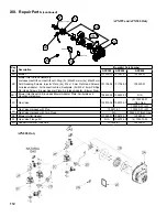
Page 110: ...110 1P 3 1P 2 1P 1 XIII Repair Parts continued 1C 1D 1E ...

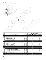
Page 111: ...uct Assembly 101725 02 N A N A 1P 2 Gas Air Intake Duct Assembly N A N A 103338 01 1P 3 Gas Air Intake Duct Weldment N A 102615 01 N A 1Q Burner Plate Insulation Warning Contains RCF Not Shown 101728 01 103610 01 1R Burner Plate Inner Seal 101729 01 1S Burner Plate Outer Seal 101730 01 1T Burner Head 101731 06 102658 01 104584 01 1U Burner Head Seal 101732 01 1V Insulation Disc Warning Contains RC...

Page 112: ...er Plate Air Intake Adapter Blower Side 101704 04 101704 05 103223 01 2B 1 Blower Inlet Repair Kit includes Blower Adapter Plate Swirlplate and Mounting Hardware 104620 04 104620 05 N A 2C Gas Valve 102975 06 102975 07 2 103224 01 Nat Gas 103299 01 LP 2D Gas Valve Harness with Plug 102971 01 103300 01 LP Gas Valve Harness with Two Plugs N A 103225 01 Nat Gas 2E Blower Outlet Gasket 101345 01 10261...

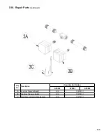
Page 113: ...escription Quantity Part Number APX399 APX500 APX800 3A Low Gas Pressure Switch N A 102702 01 3B High Gas Pressure Switch N A 102703 01 3C Gas Pressure Switch Wire Harness N A 102704 01 XIII Repair Parts continued ...

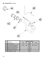
Page 114: ...B Air Pressure Switch Tubing Black 7016041 102770 01 103257 01 4C Condensate Trap Blow Molded 101239 01 4D Blocked Condensate Drain Switch 101587 01 4E Spring Clip Condensate Trap 2 101632 01 4F Rubber Grommet Condensate Trap 101595 01 4G Condensate Comp Fitting 101546 01 XIII Repair Parts continued ...

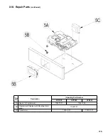
Page 115: ...air Parts continued Key No Description Quantity Part Number APX399 APX500 APX800 5A Sage2 1 Programmed 104472 01 104472 04 5B Programmed Display with Mounting Hard ware 104427 01 5C Transformer 102516 01 103193 01 ...

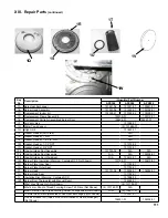
Page 116: ...116 XIII Repair Parts continued ...

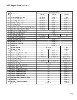
Page 117: ...9 01 6N Bracket Right Clip 101508 01 6P Rubber Pad Right Clip 101245 01 6R Draw Latch 101037 01 6S Bracket Left Clip 101507 02 N A Bracket HX Strap N A 103229 01 6T Access Panel 5 x 16 N A 102612 01 N A 6U Gasket Access Panel 5 x 16 N A 102613 01 N A 6V Bracket Gas Train N A 102611 01 103240 01 6W Gasket Access Panel 5 x 8 1 102877 01 2 102877 01 6 102877 01 6X Jacket Rear Panel N A 103230 01 6Y A...

Page 118: ...118 XIII Repair Parts continued ...

Page 119: ...9 01 6N Bracket Right Clip 101508 01 6P Rubber Pad Right Clip 101245 01 6R Draw Latch 101037 01 6S Bracket Left Clip 101507 02 N A Bracket HX Strap N A 103229 01 6T Access Panel 5 x 16 N A 102612 01 N A 6U Gasket Access Panel 5 x 16 N A 102613 01 N A 6V Bracket Gas Train N A 102611 01 103240 01 6W Gasket Access Panel 5 x 8 1 102877 01 2 102877 01 6 102877 01 6X Jacket Rear Panel N A 103230 01 6Y A...

Page 120: ...hedule 80 CPVC 90 Elbow 102192 02 1 N A 6 Schedule 80 CPVC 90 Elbow 103268 02 N A 1 6 Schedule 40 PVC 90 Elbow 103313 01 N A 2 7E 8 oz Bottle of Transition Cement 102195 01 1 7F 8 oz Bottle of Primer 102194 01 1 7G 4 x 4 CPVC PVC Vent System Connector 102183 03 1 N A 6 x 6 CPVC PVC Vent System Connector 103270 01 N A 1 7H 4 x 4 CPVC PVC Vent System Connector Gasket 102185 02 1 N A 6 x 6 CPVC PVC V...

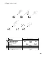
Page 121: ... 102942 03 102942 03 102942 04 8A Temperature Pressure Gauge 100282 01 8B External Gas Shut Off Valve 101615 01 816SOL0015 8C Relief Valve 81660302 81660375 8D Boiler Drain Valve 806603061 8E Boiler Stacking Brackets 2 101679 01 8F Boiler Stacking Bracket Screws 8 80860743 Outdoor Temperature Sensor Not Shown 102946 01 ...

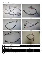
Page 122: ... 10B 10C 10D 102701 02 10A Main Low Voltage Harness 103009 02 10B High Voltage Harness 103010 02 10C Blower Power Harness 103012 01 10D Communication Harness 103011 01 10E Igniter Harness 103486 01 10F Wiring Harness Thermal Link and Burner Door Thermostat 104574 01 XIII Repair Parts continued ...

Page 123: ...2 Long sleeved loose fitting clothing 3 Gloves 4 Eye Protection Take steps to assure adequate ventilation Wash all exposed body areas gently with soap and water after contact Wash work clothes separately from other laundry and rinse washing machine after use to avoid contaminating other clothes Discard used RCF components by sealing in an airtight plastic bag RCF and crystalline silica are not cla...

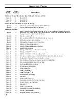
Page 124: ...dent Screen Installation Figure 11 24 Direct Vent Optional Sidewall Snorkel Terminations Figure 12 25 Direct Vent Vertical Terminations Figure 13 26 Direct Vent Vertical Terminations w Sloped Roof Figure 14 28 Vent System Field Modification to Install PVC to PP Adapter M G DuraVent Shown Figure 15 29 Flexible Vent in Masonry Chimney with Separate Air Intake Figure 16 31 Field Installation of Two P...

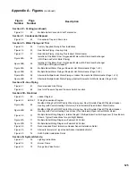
Page 125: ...Heater Page 2 of 2 Section VII Gas Piping Figure 41 61 Recommended Gas Piping Figure 42 62 Gas Inlet Pressure Tap and Pressure Switch Location Section VIII Electrical Figure 43 65 Ladder Diagram Figure 44 66 67 Wiring Connections Diagram Figure 45A 68 Modified Wiring For DHW Priority When Using Low Flow Circulator Piped Off System Header Heating with Central Heating Circulators Plus Alternately Pi...

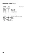
Page 126: ...Figure 56 90 Adjust Mode Screens Figure 57 99 Outdoor Reset Curve Section XI Service and Maintenance Figure 58 102 Igniter Electrode Gap Figure 59 103 Condensate Overflow Switch Orientation Section XII Troubleshooting Figure 60 105 Help Menu Section XIII Repair Parts N A Pages 110 thru 122 Appendix A Figures continued ...

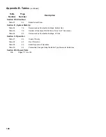
Page 127: ...ypropylene Pipe Fittings and Terminations M G DuraVent Table 10 27 Approved Polypropylene Pipe Fittings and Terminations Centrotherm Eco Table 11A 31 Burnham Commercial Vent System Components Stainless Steel Table 11B 31 Alternate Vent Systems and Vent Components Stainless Steel Table 12 32 Concentric Vent Length Table 13 32 Concentric Vent Components Applicable to APX500 Only Section VI Water Pip...

Page 128: ... 25 79 Number of Clockwise Throttle Screw Turns for LP Conversion Table 26 80 Recommended Combustion Settings LP Gas Section X Operation Table 27 82 Order of Priority Table 28 83 Frost Protection Table 29 85 Boiler Sequence of Operation Table 30 92 Parameters Changed Using the Boiler Type Parameter Selections Section XIII Repair Parts N A Pages 111 thru 122 Appendix B Tables continued ...

Page 129: ...129 SERVICE RECORD DATE SERVICE PERFORMED ...

Page 130: ...130 SERVICE RECORD DATE SERVICE PERFORMED ...

Page 131: ...131 SERVICE RECORD DATE SERVICE PERFORMED ...
Page 132: ...rformance as a result of faulty workmanship in the installation which liability is expressly disclaimed e Boilers parts or accessories installed outside the 48 contiguous United States the State of Alaska and Canada f Damage to the boiler and or property due to installation or operation of the boiler that is not in accordance with the boiler installation and operating instruction manual g Any dama...

Reviews: