78
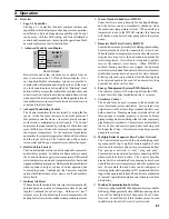
Figure 52: Burner Flame
probe directly into flue sensor port. Reinstall the sensor
and the cap upon combustion testing completion.
Check CO
2
(or O
2
) and CO at both high and low fire.
The boiler may be locked into high of low fire as
follows:
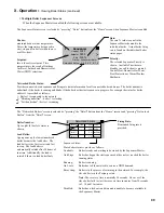
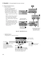
1. To lock the boiler in high fire enter the Manual
control screen by first entering the Adjust screen. To
access the Adjust screen, touch the Adjust button,
then Login using the contractor password “076”.
Press Save and then select the adjust button. Enter
the Manual Control button and select “High”.
Allow the boiler to operate for approximately 5
minutes before taking combustion readings.
2. To lock the boiler in low fire select “Low” from
the Manual Control screen. Allow the boiler to
operate for approximately 5 minutes before taking
combustion readings.
3. Normal modulation of the boiler will only occur
after the “Auto” button is selected in the Manual
Control screen.
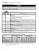
Typical CO
2
readings are shown in Table 24 (Natural
Gas or Table 26 (LP Gas).
Warning
Each apex Series boiler is tested at the factory and
adjustments to the air fuel mixture are normally
not necessary. improper gas valve or mixture
adjustments could result in property damage,
personal injury, or loss of life.
iX. System Start-up
(continued)
value listed on the boiler rating label. If a boiler
is equipped with two gas valves, throttle screw
adjustments must be done to both gas valves equally
and simultaneously.
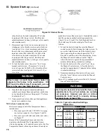
9. If measured input is too low, increase input rate by
rotating gas valve throttle screw counterclockwise
(see Figure 53) in ¼ turn increments and checking
the rate after every adjustment until the measured
input rate value falls within 88% to 100% of the
value listed on the boiler rating label. If a boiler
is equipped with two gas valves, throttle screw
adjustments must be done to both gas valves equally
and simultaneously.
10. To lock the boiler in low fire, select “Low” from
manual control screen. If measured % O
2
on LF,
is out of spec (see Table 24 or 26), then turn offset
screw clockwise (see Figure 53) to lower % O
2
or
vice versa.
Warning
Offset screw on each apex Series boiler is
adjusted at the factory to the specification. DO
nOT touch the offset screw if measured 0
2
on Low
Fire is in the spec (see Table 24 or 26).
11. Once the boiler input rate adjusted/confirmed,
recheck main burner flame and perform combustion
test as described below (see Paragraph L “ Perform
Combustion Test”).
12. Upon completion, return other gas-fired appliances
to previous condition of use.
M.
Perform Combustion Test
Boilers are equipped with Flue Temperature Sensor
installed into:
• Flue sensor port of boiler CPVC/PVC two-pipe
vent system connector - See Figures 5 and 16.
• Flue sensor port of boiler concentric vent collar -
see Figure 17.
Remove Flue Temperature Sensor and insert the
analyzer probe through Flue Temperature Sensor
silicon cap opening, or if required, remove also the Flue
Temperature Sensor silicon cap and insert the analyzer
Boiler
Model
altitude range
0 - 7000 Ft.
% CO
2
% O
2
range
CO, PPM
APX399
9.9 - 8.2
(High Fire)
9.3 - 7.9
(Low Fire)
3.5 - 6.5
(High Fire)
4.5 - 7.0
(Low Fire)
Less than
100 PPM
APX500
APX800
9.3 - 7.9
(High Fire)
9.3 - 7.9
(Low Fire)
4.5 - 7.0
(High Fire)
4.5 - 7.0
(Low Fire)
Table 24: Typical Combustion Settings,
natural gas
Summary of Contents for Apex APX399
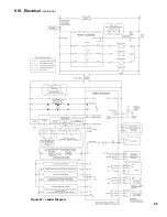
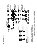
Page 65: ...65 VIII Electrical continued Figure 43 Ladder Diagram ...
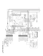
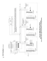
Page 66: ...66 VIII Electrical continued ...
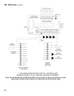
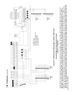
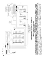
Page 67: ...67 Figure 44 Wiring Connections Diagram VIII Electrical continued ...
Page 110: ...110 1P 3 1P 2 1P 1 XIII Repair Parts continued 1C 1D 1E ...
Page 116: ...116 XIII Repair Parts continued ...
Page 118: ...118 XIII Repair Parts continued ...
Page 129: ...129 SERVICE RECORD DATE SERVICE PERFORMED ...
Page 130: ...130 SERVICE RECORD DATE SERVICE PERFORMED ...

