58
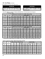
Boiler Model
Boiler Supply
Connection, i
nch, FPT
Boiler return
Connection, i
nch, FPT
n
ear-Boiler Piping Supply Pipe Size,
inch
(Note 2)
n
ear-
Boiler Piping return Pipe Size, i
nch
(Note 2)
Max
a
llowa
ble
Flow thru
Boiler
,
g
PM @ 20°F
D
T
Flow
,
g
PM
@ 25°F
D
T
Min
Req’d
Flow thru
Boiler
,
g
PM
@ 35°F
D
T
a
lliance
SL
Models to be installed a
s Part of
n
ear-Boiler Piping
a
lliance SL
Coil
Required
Flow
r
ate,
g
PM
a
lliance SL
Coil Head Loss, Ft @
Required
Flow
r
ate
Combined
Boiler
,
a
lliance SL
& Piping Loop Head Loss, Ft
*r
ecommended
Circulator Make &
Model for alliance SL
installed as Part of
n
ear-Boiler Piping
r
eference Figure
n
otes
a
PX399
1-1/2
1-1/2
2
2
37.7
30.2
21.5
SL27
6
9
NA
*
Not
Recommended
(see Notes 1
and 2)
40A
& 40B
40A
& 40B
Note 1
Note 2
SL35
6
9
SL50
6
9.5
SL70
6
10
SL1
19
14
17.0
a
PX500
47.2
37.8
27.0
SL27
6
9
SL35
6
9
SL50
6
9.5
SL70
6
10
SL1
19
14
17.0
a
PX800
2
2
2½
2½
76.0
60.8
43.4
SL27
6
9
SL35
6
9
SL50
6
9.5
SL70
6
10
SL1
19
14
17.0
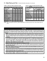
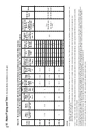
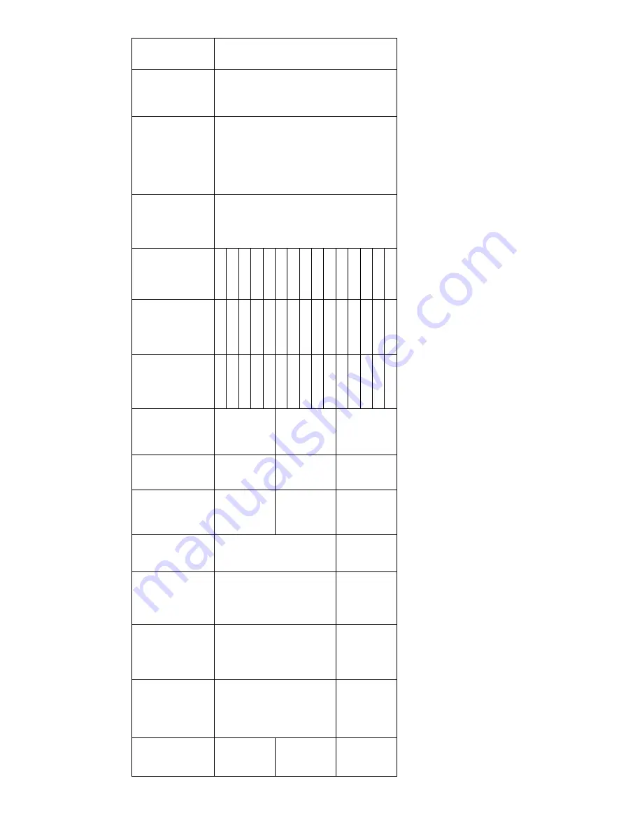
Table 18:
r
ecommended Circulator Models for
a
pex (
a
PX) Boilers and
a
lliance SL
indirect W
ater Heaters
Installed as Part of Near-Boiler Piping Up to 75 Ft. Equivalent Length - Domestic Hot W
ater Circulator
n
OTES
:
Note 1:
All
Alliance SL
Coil Flow Rates are below Min Required Flow Rate thru Boiler corresponding to boiler maximum firing rate.
These
Alliance models can only be installed as separate heating zone of
f system header - see
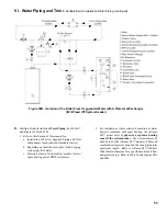
Figure 39A
and 39B for IWH piping.
Indirect W
ater Heater Circulator must be selected by an installer based on
Alliance SL
required coil flow and corresponding coil head loss shown as well as total equivalent length of such separate zone.
Note 2:
*
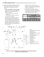
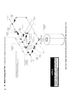
The IWH may be installed as part of Boiler piping when boiler DHW modulation rate (input) is adjusted to closely match the IWH rated heating capacity required to satisfy DHW demand (see Figures 40A
and 40B).
IMPOR
TANT
– Shared or Isolated DHW Demand
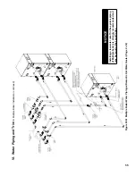
When the IWH parameter is set to “Primary Piped”, the Sequence Master will be sequencing all required boilers to satisfy the DHW setpoint (default 180°F). Do not use the “Boiler Piped” parameter for 500 and 800 models, unless IWH is piped of
f an individual boiler having DHW modulation rate (input) adjusted to closely match the IWH rated heating capacity required to satisfy DHW demand. Otherwise, piping an IWH of an individual boiler could
cause higher than normal velocities or DT’
s thru that boiler because of required IWH flow
. For commercial applications, it is recommended to pipe IWH’
s of
f the common header piping.
A header sensor must be installed to
prevent rapid header temperature rise when the Sequence Master is sequencing all required boilers to satisfy the DHW setpoint (default 180°F).
Note 3: Near-Boiler Piping Size shown is based on 2 to 5.5 Ft/sec velocity range to avoid potential noise and pipe erosion.
Vi
. W
ater Piping and T
rim
E. Multiple Boiler Installation (continued)
Summary of Contents for Apex APX399
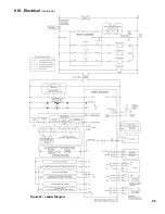
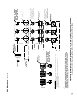
Page 65: ...65 VIII Electrical continued Figure 43 Ladder Diagram ...
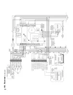
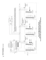
Page 66: ...66 VIII Electrical continued ...
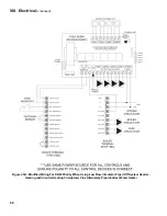
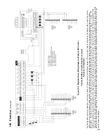
Page 67: ...67 Figure 44 Wiring Connections Diagram VIII Electrical continued ...
Page 110: ...110 1P 3 1P 2 1P 1 XIII Repair Parts continued 1C 1D 1E ...
Page 116: ...116 XIII Repair Parts continued ...
Page 118: ...118 XIII Repair Parts continued ...
Page 129: ...129 SERVICE RECORD DATE SERVICE PERFORMED ...
Page 130: ...130 SERVICE RECORD DATE SERVICE PERFORMED ...

