9
Inspection and maintenance
Logano plus GB402 - Subject to technical modifications!
50
9.9.1
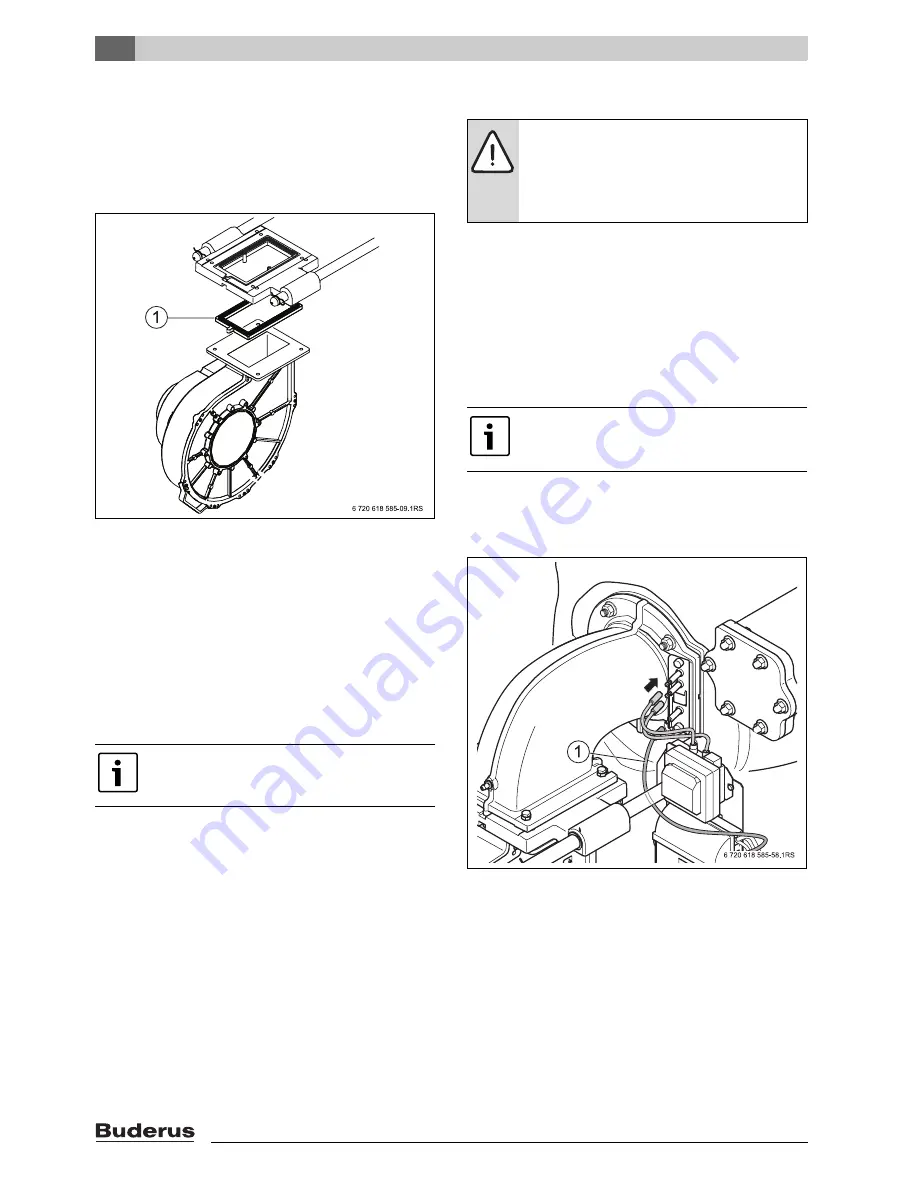
Fitting the fan
B
Push the fan underneath the screws undone on the
underside of the carriage. Lower the fan slightly at the
front and insert a new gasket [1] into the groove in the
carriage.
B
Secure the fan to the carriage using all 4 screws.
Fig. 62 Replacing the fan/carriage gaskets
B
After the fan installation, check the gasket for correct
seating.
9.9.2
Fitting the ventilation air collector and the
gas valve
B
Secure the mounting plate on the fan. Position the rear
semi-shell of the ventilation air collector on the studs of
the mounting plate and push the fan inlet nozzle over
the studs towards the semi-shell, then secure it.
B
Push the impeller onto the studs, so that the marking
points upwards.
B
Secure the front semi-shell with clips to the ventilation
air collector.
B
Push the compensation hose onto the ventilation air
collector.
B
Secure the gas valve with the nozzle plate on the studs.
9.9.3
Installing the burner
B
Insert the gasket on the top of the carriage.
B
Insert the O-ring into the mixture manifold.
B
Insert the burner together with the mixture manifold into
the boiler combustion chamber.
B
Push the carriage towards the boiler block.
B
Secure the mixture manifold on the carriage using
4 screws.
B
Secure the mixture manifold at the front section of the
boiler using 4 nuts.
B
Plug all necessary cables into the gas valve and fan,
and the plug-in connections into the electrode block.
During this step, route ionisation cable [1] as shown
in Fig. 63 (below the guide rod).
Fig. 63 Plug-in connection at the electrode block
9.9.4
Fitting the gas line to the gas valve
B
Insert a new O-ring into the gas valve flange.
B
Secure the gas valve to the fan using 4 screws.
B
Secure the flange of the gas connection again to the
gas valve using 4 screws.
When fitting the impeller ensure that the
marking points upwards.
DANGER:
Risk to life from escaping flue gas!
B
During installation, look out for faulty
gaskets and ensure they are seated
correctly. Replace faulty gaskets.
B
Observe the order of assembly described.
There is an indicator window on the top of the
flange so you can check from the outside that
a gasket has been inserted.


