6
Installation
Logano plus GB402 - Subject to technical modifications!
27
Inserting the function module
In total, up to 2 function modules can be plugged into the
control unit. Only one mixer module can be used as part
of the system. For further supplementary modules, you
require one complete enclosure (accessory).
B
Guide the outer rear hooks of the function module into
the tabs on the control unit [1].
B
Press the front of the module downwards.
Fig. 23 Inserting the function module
Fitting the cover
B
Push the control unit cover down into the guide rails.
B
Tighten two screws to secure control unit cover.
Fig. 24 Fitting the cover
6.8
Fuel connection
B
Install gas tap R2” [2] in the gas line (GAS). During this
operation, prevent the gas line inside the boiler from
becoming twisted.
B
Connect compensator [1] (recommended) to the gas
tap.
B
Connect the gas line to the gas connection free of
stress.
B
Secure the gas line with pipe clips so that the gas
connection is free from any stresses.
B
Close the gas tap.
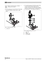
Fig. 25 Gas connection
1
Compensator
2
Gas tap (here with thermally activated shut-off equipment)
3
Pipe clip
Observe the installation instructions of the
function module.
7 747 010 720-35.1RS
DANGER:
Risk to life from explosion of
flammable gases!
B
Work on components in contact with gas
must only be carried out by certified gas
fitters.
B
Observe all local regulations in connection
with the gas connection.
B
Seal in the gas connections with an
approved sealant.
Subject to local regulations, install thermally
activated shut-off equipment.
In addition, we recommend the installation of
a gas filter and compensator in the gas line in
accordance with local regulations.
For higher gas supply pressures than shown
in Tab. 10, page 33, Buderus offers
additional gas pressure regulators as
accessories.


