background image

Operation


- 3.46 - 

SMART 200 TSS


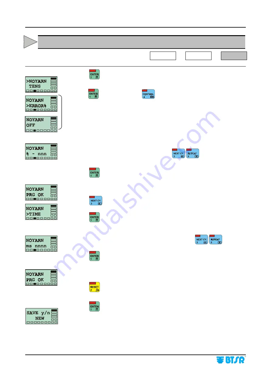
NOYARN  -  Creating a New Article 

Characteristics of the Yarn Missing Failure 

SETUP 

#

#

#

#


NEW 

#

#

#

#

  NOYARN 


Press 

 to have access to the function. 


Press


 to continue, or press 

 to disable/enable this parameter. 


Set the increasing percentage with respect to the reference nominal tension 

that shall be interpreted as yarn missing, using 


[Default: -75%]


Press 

 to confirm the entered value. 

 
This screen, displayed for a few seconds indicates that the previously set 
parameter has been programmed correctly. 

Press 

 to select the Minimum Duration of the Yarn Missing failure 

(TIME)

Press 

 to continue. 


Set the Minimum Duration of Yarn Missing failure, using 


[Default: 10.0 ms]


Press 

 to continue. 

 
This screen, displayed for a few seconds indicates that the Minimum Duration 
parameter has been programmed correctly. 

Press 

 once to return to the Article Parameters Menu, or two times to store all 

parameters of the article and exit the Article Creation function. 

Press 

 to save the Article into the data base. 


B6 

Summary of Contents for SMART 200 TSS

Page 1: ...SMART 200 TSS TS5 YARN CONTROL SYSTEM Operating Manual Rev 2 0 July 2003 ENGLISH ...

Page 2: ...notice For any technical or commercial problem please contact your local BTSR dealer or call directly BTSR customer service centre We will be glad to meet your needs Thank you for your trust and good job The product described herein is compliant with the requirements of 89 336 EEC EMC Directive and 73 23 EEC Low Voltage Directive All BTSR products are covered by patents and adopt exclusive profita...

Page 3: ... 3 4 Function of the TS5 Sensors 3 4 TS5 Sensor Types 3 5 Eyelet models 3 5 Technical Characteristics of TS5 sensor 3 6 Electrical Connections 3 7 Mounting positions 3 7 Interface specification 3 8 Interpretation of the signaling lights located on the sensors 3 9 Parameters that affect the sensor detection features 3 10 Other factors that may affect the control 3 12 Preliminary operations for usin...

Page 4: ...e Characteristics of Max Tension Threshold Exceeded failure 3 42 TENS L Creating a New Article Characteristics of Min Tension Threshold Exceeded failure 3 43 PEAK H Creating a New Article Characteristics of Max Tension Peak Exceeded failure 3 44 PEAK L Creating a New Article Characteristics of Min Tension Peak Exceeded failure 3 45 NOYARN Creating a New Article Characteristics of the Yarn Missing ...

Page 5: ...erformed by the individual TS5 sensors TSQ On textile machines such as beam warping machines quilting machines embroidery machines etc which from time to time may use a number of yarns not necessarily equal to the number of installed TS5 sensors In this case besides the article s Data Base function the SMART 200 TSS terminal performs a real time control function on the number of yarns used by the ...

Page 6: ...pe of eyelet used etc For your convenience within this manual we will always use the generic term TS5 While scrolling through features that can be activated from the SETUP and WORK menus this symbol indicates the procedure that describes the specific feature The same symbol is reported at the beginning of the page which describes in details the function itself Within the operating procedures secti...

Page 7: ...gramming TSS q TSS q TSS mode TSs Q System Working Mode selection either TSS or TSQ TSs Q TSQ mode ST NCo NCo normally closed ST NcO Stop Output programmable as Normally Closed NC or Normally Open NO contact NcO normally open LK ulk LK touch light disabled lk UKL Enabling ULK or disabling LK the touch light button ULK touch light enabled EN NCo NCo normally closed EN NcO Enable signal programmable...

Page 8: ...Introduction I 4 SMART 200 TSS Page intentionally left blank ...

Page 9: ...ol requirements in addiction it has the function of displaying either globally or selectively the counters that record the different types of defects detected by the sensors Furthermore the possibility to print a report containing the summary of failures detected by the sensors Production Report offers a valuable support for keeping and improving the quality level of production Special Features of...

Page 10: ...e SMART control terminal using specific single connector and doubler cables Automatic numbering BTSR Patents The identification of sensors is performed by the system by means of an automatic numbering procedure Programmable Functions The system allows programming and saving all the quality control characteristics associated with various articles Parameters can be programmed either globally to all ...

Page 11: ...0 5 Vdc Auto calibration function Auto calibration of sensor STOP output protection Protection against over voltages and short circuits STOP output max current 200 mA continuous 500 mA peak Activation delay Programmable from 1 to 250 sec Signalling With integrated LED s Dimensions 50 x 25 x 12 5 mm Temperature range 10 60 C Installation The installation of the SMART 200 TSS system depends on the t...

Page 12: ...l data and installation 2 2 SMART 200 TSS Interface Connectors on SMART 200 TSS Concerning all electrical systems it is a recommended rule to ensure that the ground cable GND is connected to the sensor support ...

Page 13: ...T 200 TSS 2 3 Connection Example for Generic Applications on Rewinding Doubling Cone Winder Machines etc TSS Concerning all electrical systems it is a recommended rule to ensure that the ground cable GND is connected to the sensor support ...

Page 14: ...MART 200 TSS Connection Example for Generic Applications on Warping Machines Quilting Embroidery Machines TSQ Concerning all electrical systems it is a recommended rule to ensure that the ground cable GND is connected to the sensor support ...

Page 15: ... SMART 200 TSS PSU 10A and MA2FE8 Doubler Cable FE100 FEC Length 100 cm FE200 FEC Length 200 cm FE300 FEC Length 300 cm FE400 FEC Length 400 cm Doubler Cable from one Male to two Female with Independent Stop and Ground outputs to Connect a Solenoid valve Cutter Alarm Signalling Light etc MA2FE8 Extension Cable 4x0 35 mm with Male and Female connector MA50 FEC Length 50 cm MA100 FEC Length 100 cm M...

Page 16: ...Technical data and installation 2 6 SMART 200 TSS Page intentionally left blank ...

Page 17: ...of straight forward messages which can be understood clearly and immediately On the top left hand side of each button there is a red LED which indicates that the button is pressed down The display screen includes two separate zones used respectively for displaying messages to the operator during the system programming and administration phases and for signaling the operating status and levels in w...

Page 18: ...the character displayed where the cursor is located according to the following cyclic sequence When entering numeric data for example the number of sensors it allows you to increase the numeric value of the field If it is held down continuously the numeric field increments more rapidly 4 CONTROL Button During parameter programming it allows changing the position of the cursor 5 REPEAT Button Durin...

Page 19: ...ontext in which you are working on the right hand side and bottom side of the operator message area 16 rectangular boxes labels are implemented They display the operating status of the system and the hierarchic level of the menu at which you are operating More specifically the PROGRAM label indicates that you are operating in one of the following modes configuration programming or data transmissio...

Page 20: ...on of quality control of any kind of yarn application As the TS5 are parametric devices it is possible to set freely error percentages on tension and the duration of anomalies The TS5 devices are very easy to use as they are ready to accommodate a large variety of accessories that make them suitable to the quality control of any type of yarn Function of the TS5 Sensors The TS5 sensors provide the ...

Page 21: ...ic needs of individual installations applications The following diagram shows a detailed coding rule of the available sensors depending on possible variables Example TS5 D500DD TS5 sensor 500 grams weight with model DD eyelet Diamond finishing Eyelet models A BC 0 012 B BC 0 020 C BC 0 024 D BC 0 041 E BC 0 048 ...

Page 22: ...Operation 3 6 SMART 200 TSS Technical Characteristics of TS5 sensor Sizes mm ...

Page 23: ...Operation SMART 200 TSS 3 7 Electrical Connections Mounting positions 1 VCC Red 2 STOP Green 3 GND White 4 GND White 5 RX TX Yellow 6 Uscita Anal Brown 7 RX TX Black 8 Enable Blue ...

Page 24: ...ROL Green LED flashing resumes the normal control Green LED permanently lit Electrical Characteristics of the STOP Signal Protection against short circuits Collector continuous current 200 mA Peak collector current 500 mA Vce 1 2V with I_ collector 500mA ENABLE Signal Function The ENABLE signal represents for the TS5 sensor an Input signal having two different effects on its operation depending on...

Page 25: ... due to a fault detection a machine position running correctly a standstill machine position Interpretation of the signaling lights located on the sensors Green Led ON Sensor under normal control No defects detected by the sensor either in Control on Monitor mode Green LED FLASHING Sensor under automatic numbering procedure Sensor in Delay Control phase Sensor disabled via HW ENABLE signal or SW R...

Page 26: ...this program are represented by the settings related to the article which is being controlled i e the settings that can be defined changed and loaded into the sensors by means of the SMART 200 TSS system TENS Nominal Reference Tension TENS H Max Tension Threshold TENS L Min Tension Threshold PEAK H Max Tension Peak PEAK L Min Tension Peak NOYARN Missing Yarn The quality control performed by TS5 se...

Page 27: ...max peak with respect to the nominal tension TENS TIME Minimum duration of error condition to signal the failure PEAK L This parameter indicates the Min Peak Value expressed as negative percentage value with respect to the reference tension TENS below which a failure condition will be signalled The following two values must be specified ERROR Negative error percentage min peak with respect to the ...

Page 28: ...ed green LEDs NOYARN failure continuous flashing red LED STOP output activation In Monitor mode as soon as the failure condition disappears the sensor automatically resumes the normal operation and turns on the green LED CONTROL No Failure Green LED lit TENS H failure 1 flash red LED STOP output activation PEAK H failure 2 flashes red LED STOP output activation TENS L failure 1 flash red green LED...

Page 29: ...nt values with respect to the TENS reference and will always remain unchanged throughout the entire yarn processing cycle This option could be critical if for any reason one or more sensors operate with an actual reference tension very close to the minimum TENS L or maximum TENS H limits defined for the article RELABS RELATIVE ABSOLUTE mode All calculations are carried out according to a reference...

Page 30: ...he memory of the SMART terminal Press to reset the error The system will erase all settings entered by the user and will reload the default values If the error persists please refer to Troubleshooting chapter If the system displays one of the messages that you can see on the left hand side of this page it means that the terminal is working correctly and that it is possible to activate one of the f...

Page 31: ...and CONTROL allows the activation of control mode WORK allows the completion of tasks GRAPH allows the completion of tasks The following five operating sequences show how to activate the four items of the main menu and how to choose the desired function within each item The following pages will describe in detail each task providing all the necessary information to correctly perform the tasks them...

Page 32: ...Operation 3 16 SMART 200 TSS Enabling the SETUP Menu Functions CONFIG ...

Page 33: ...Operation SMART 200 TSS 3 17 Enabling the SETUP Menu Functions NEW MODIFY ERASE Enabling the WORK Menu Function ...

Page 34: ...Operation 3 18 SMART 200 TSS Enabling the GRAPH Menu Function ...

Page 35: ...es D TOT L PL xxx DEV TOT PL xxx Total Number of Peak Low failures D TOT L NY xxx DEV TOT NY xxx Total Number of Missing Yarn failures D nnn L TH xxx DEV nnn TH xxx Number of Tension High failures on device nnn D nnn L TL xxx DEV nnn TL xxx Number of Tension Low failures on device nnn D nnn L PH xxx DEV nnn PH xxx Number of Peak High failures on device nnn D nnn L PL xxx DEV nnn PL xxx Number of P...

Page 36: ...RT 200 TSS By pressing or it is possible to either increase or decrease the XXX value until the number of sensors actually connected to the system is reached At this point press to start the numbering operation This screen indicates that the phase of automatic sensor numbering is starting YYY shows the total amount of sensors to be numbered ZZZ shows the number of the first sensor and subsequently...

Page 37: ...r added sensor using and Replacing a Sensor Example 1 If the machine has 12 sensors and the sensor No 8 has been replaced the display will show this data Press until the right field where the cursor is positioned shows 008 With a finger skim the Touch Light area of the sensor No 8 and check that the sensor LED goes from flashing green to red The replaced sensor will now be identified as sensor No ...

Page 38: ...SIDE disabled Sensors 1 2 3 98 99 100 2 Number of installed sensors 100 option SIDE enabled Sensors 1A 2A 3A 48A 49A 50A 1B 2B 3B 48B 49B 50B Once you have selected the SIDE function from CONFIG menu press to have access to the function If necessary press to select the desired option SIDE A B machine logically subdivided into 2 sides A and B SIDE OFF logically subdivision disabled OFF Press to con...

Page 39: ...s own position TSQ Complete real time Tension Control system The whole machine will be controlled by the SMART 200 TSS terminal after a preliminary Learn cycle Once you have selected the TSS q function from CONFIG menu press to have access to the function If necessary press to select the desired option either TSS or TSQ Press to confirm the selection It means that currently the TSS option is selec...

Page 40: ...aving 40 sensors installed you could choose to program the Monitor mode only on sensors 7 to 20 in this way sensors 1 to 6 and 21 to 40 will automatically be programmed in Control mode Once you have selected the MO CTR function from CONFIG menu press to have access to the function If necessary press to select the desired option either CONTROL CONFIG to activate the CONTROL function or MONITOR CONF...

Page 41: ... the XXX YYY range the SMART 200 TSS terminal will automatically update the situation thus bringing back to Control mode the sensors which are no longer included in the new range Only one XXX YYY range may be programmed Press to confirm the set values The display shows for a few seconds the messages CONTROL WAIT CONTROL PRG OK or MONITOR WAIT MONITOR PRG OK to indicate that the function has been p...

Page 42: ...K UNLOCK condition set with this function Once you have selected the LK ULK function from CONFIG menu press to have access to the function If necessary press to select the desired option either UNLOCK CONFIG to enable the button currently disabled or LOCK CONFIG to disable the button currently enabled Press to confirm Either UNLOCK WAIT UNLOCK PRG OK or LOCK WAIT LOCK PRG OK will appear to indicat...

Page 43: ...signal operation please refer to the Interface Specification paragraph Once you have selected the ST NCO function from CONFIG menu press to have access to the function If necessary press to select the desired option either STOP NO CONFIG or STOP NC CONFIG Press to confirm the selection The display shows for a few seconds the messages STOP NO WAIT and STOP NO PRG OK or STOP NC WAIT and STOP NC PRG ...

Page 44: ...E signal operation please refer to the Interface Specification paragraph Once you have selected the EN NCO function from CONFIG menu press to have access to the function If necessary press to select the desired option either ENAB NO CONFIG or ENAB NC CONFIG Press to confirm the selection The display shows for a few seconds the messages ENAB NO WAIT and ENAB NO PRG OK or ENAB NC WAIT and ENAB NC PR...

Page 45: ...anual activation of the sensor this will start the actual operation i e to signal possible defects only when such delay time has elapsed The delay time is indicated by the green Led flashing Once you have selected the D_CNTR function from CONFIG menu press to have access to the function Set the desired value 1 250 seconds using or Press to confirm the entered value The D_CNTR WAIT message shown fo...

Page 46: ... access to the function XXX indicates the number of first sensor on which to perform the offset YYY indicates the number of last sensor on which to perform the offset SIDE A B indicates the machine sides A B only if the SIDE option is enabled moves the cursor from XXX field to YYY field increases the field pointed by the cursor decreases the field pointed by the cursor 3 sec switches from side A t...

Page 47: ...scription on page 3 13 Once you have selected the ABS RELABS function from CONFIG menu press to have access to the function If necessary press to select the desired option ABS CONFIG or RELABS CONFIG Press to confirm the selection The display show for a few seconds the messages ABS WAIT and ABS PRG OK or RELABS WAIT and RELABS PRG OK to indicate that the function has been programmed correctly Pres...

Page 48: ... from 1 to 7 alphanumeric characters using the following buttons Increases the character where the cursor is positioned Decreases the character where the cursor is positioned Moves the cursor one position to the right Confirms and stores the code which has been set If no code is entered the function is disabled and you will not be asked for an access code when entering the SETUP and WORK menus Pre...

Page 49: ...ers using the following buttons Increases the character where the cursor is positioned Decreases the character where the cursor is positioned Moves the cursor one position to the right Confirms and stores the code which has been set If no code is entered the function is disabled and you will not be asked for an access code when entering the LEARN function Press once to return to the CONFIG Menu or...

Page 50: ...DD day MM month YY year dd mm yy New values if needed Increases the value Decreases the value Alternatively selects dd mm yy fields Once you have checked and setup if necessary the date press to confirm HH MM Read values HH hours MM minutes hh mm New values if needed Increases the value Decreases the value Alternatively selects hh and mm fields Once you have checked and setup if necessary the hour...

Page 51: ...s screen indicates that the sensor test is going to start Press to continue DEV XXX or A XXX if the SIDE option is enabled indicates the sensor which is being tested initially sensor no 1 Check that the Red LED of sensor XXX is flashing and there are no other sensors with the Red LED FLASHING If the Red LED of the sensor that should respond to the number XXX is not flashing it means that the senso...

Page 52: ... signaled by the sensors Press until the TEST CONFIG menu option is displayed Press to have access to the Test function Press to select the Communications Test This screen indicates that the Communications Test is going to start Press to begin the test From this moment on the system communicates repeatedly with all connected sensors The running test status is signaled by the flashing red LED insid...

Page 53: ... until the VERS TEST menu item appears Press to continue DEV XXX or D XXX A if the SIDE option is enabled Number of TS5 device n n Software version loaded on XXX device Press to select in sequence all the connected devices and check the software version loaded Press to switch from Side A to Side B and vice versa Press to return to the VERS TEST screen Press to select the UPG TEST menu item Press t...

Page 54: ...ss to execute the updating The selected sensors will be automatically updated one after the other and the field xxx will automatically increase until it reaches the value set as yyy in the previous step Press once to leave this function or press it twice to return to the Main Menu ...

Page 55: ... TENS 0 1 1000 0 default 5 0 gr Parameter ERROR TIME TENS H 1 300 default 30 10 5000ms default 100 ms TENS L 1 300 default 30 10 5000ms default 100 ms PEAK H 1 300 default 50 0 5 100 0ms default 10 0ms PEAK L 1 300 default 50 0 5 100 0ms default 10 0ms NOYARN 1 100 default 75 10 5000ms default 10 0ms Once you have selected the SETUP NEW function you are prompted to enter the name of the new articl...

Page 56: ...S L PEAK H PEAK L and NOYARN can be selectively disabled OFF or re enabled pressing the CONTROL button Now you will have to program the sequence of tension control parameters related to the article being created TENS TENS H TENS L PEAK H PEAK L NOYARN ...

Page 57: ...ess to have access to the function Set the reference nominal tension for the article being created using Default 5 0 gr Press the entered value This screen displayed for a few seconds indicates that the previously set parameter has been programmed correctly Press to select the next parameter TENS H B1 ...

Page 58: ...xceeded using Default 30 Press to confirm the entered value This screen displayed for a few seconds indicates that the previously set parameter has been programmed correctly Press to select the Minimum Duration of the failure TIME Press to continue Set the Minimum Duration of Max Tension Threshold Exceeded failure using Default 100 ms Press to continue This screen displayed for a few seconds indic...

Page 59: ...xceeded using Default 30 Press to confirm the entered value This screen displayed for a few seconds indicates that the previously set parameter has been programmed correctly Press to select the Minimum Duration of the failure TIME Press to continue Set the Minimum Duration of Min Tension Threshold Exceeded failure using Default 100 ms Press to continue This screen displayed for a few seconds indic...

Page 60: ...eded using Default 50 Press to confirm the entered value This screen displayed for a few seconds indicates that the previously set parameter has been programmed correctly Press to select the Minimum Duration of the failure TIME Press to continue Set the Minimum Duration of Max Tension Peak Exceeded failure using Default 10 0 ms Press to continue This screen displayed for a few seconds indicates th...

Page 61: ...eded using Default 50 Press to confirm the entered value This screen displayed for a few seconds indicates that the previously set parameter has been programmed correctly Press to select the Minimum Duration of the failure TIME Press to continue Set the Minimum Duration of Min Tension Peak Exceeded failure using Default 10 0 ms Press to continue This screen displayed for a few seconds indicates th...

Page 62: ... screen displayed for a few seconds indicates that the previously set parameter has been programmed correctly Press to select the Minimum Duration of the Yarn Missing failure TIME Press to continue Set the Minimum Duration of Yarn Missing failure using Default 10 0 ms Press to continue This screen displayed for a few seconds indicates that the Minimum Duration parameter has been programmed correct...

Page 63: ...ting it among those already existing inside the data base using ERASE Erasing an existing Article SETUP ERASE This function allows removing from the data base a previously created article Press to have access to the function Select the article to be removed using and press to continue Press to confirm the erase function During the erase process the OK WAIT message is displayed If you try to erase ...

Page 64: ...s the first sensor on which the article has been loaded KKK shows the last sensor on which the article has been loaded L indicates the machine side either A or B if the SIDE option is enabled Press to select to the next article Press to leave the function When scanning of all the articles currently loaded has finished the END SCAN message appears to indicate that there are no other articles beyond...

Page 65: ...elected article in particular XXX shows the first sensor YYY shows the last sensor Increases the number where the cursor is positioned Decreases the number where the cursor is positioned Moves the cursor between XXX and YYY fields Press and hold down for 3 seconds to switch from Side A to Side B and vice versa if the SIDE option is enabled Press to confirm the setting and go to the next screen Pre...

Page 66: ... mode If the operating mode is TSS and the sensor working mode is RELABS after the article s parameters loading the self learning LEARN procedure will be activated Press to continue Press to continue This screen indicates that theLEARN phase is in progress This screen indicates that the learn phase has been correctly completed At this point the system will automatically return to the initial LOAD ...

Page 67: ...on Press once or several times until the name of the required article that you wish to unload from the sensor appears YYY KKK sensor interval from which to unload the article L indicates the machine side either A or B if the SIDE option is enabled At this point press to have access to the function Press to unload the settings of the article from the sensors which were previously detecting that art...

Page 68: ...e function Press to activate the graphic display Increments yy Decrements yy Press to exit If the SIDE function is active then the Dyy indication will become Ayy or Byy where A and B represent the machine sides To switch from A and B press CONTROL H 1 Device number selectable using Horizontal bar showing in real time if the detected tension is included between the Minimum and Maximum acceptable va...

Page 69: ...ave the possibility to choose the reference device against which to perform the comparison as well as the number of devices Histogram s bars to be compared 8 12 or 16 REF 1 REF 7 REF REF REF REF 1 REF 11 REF 1 REF 15 H 2 TENSH threshold TENSL threshold BARS 8 Selectable with Selectable with BARS 12 Selectable with BARS 16 Selectable with PEAKH limit PEAKL limit TENSH threshold TENSL threshold PEAK...

Page 70: ...ss to start the function Choose the reference sensor nnn using Choose the number of bars sensors to be displayed 8 12 16 using 3 sec to select the desired machine side either A or B if the SIDE function is active Press to activate the graphic display Press once to exit the graphic function and return to REF nnn BARS x screen or 2 times to return to the Main Menu ...

Page 71: ...r and it is signaled by the status of Leds built in inside the TS5 sensors and by the Led built in inside the ENTER button of SMART 200 TSS terminal When the system is in Control status CONTROL message blinking and symbol displayed in sequence on terminal display press to access the LEARN function Press to continue Press to continue This message indicates that the learn operation has been Reserved...

Page 72: ...sage re appears and the green Leds remain permanently lit on the sensors where the yarn running was detected within the setup tolerance limits These will be the sensors enabled during the subsequent working phases while the other sensors where the correct yarn running was not detected will have the green Led off and will be excluded from the control ...

Page 73: ...in the report L Machine Side either A or B if the SIDE function is active Select the desired range using 3 sec to select the desired machine side either A or B if the SIDE function is enabled Once you have selected the desired positions press to start the printout This screen indicates that the printout is in progress When the printing is completed the REPORT xxx yyy screen will re appear allowing...

Page 74: ...Operation 3 58 SMART 200 TSS Production Report Example ...

Page 75: ...n again a number to all the sensors The sensors numbering procedure fails the number YYY does not increase in the screen DEV Y XXX YYY Problems on the communications line Check that the sensors are correctly connected Check for locked sensors green and red LED simultaneously ON Power off and on the system If the problem persists replace the sensor If the problem persists connect a set of sensors a...

Page 76: ...etection features to remain unaffected even when some traces of dirt are present However it is recommended to clean the sensors periodically For maintenance operations on printer device i e paper roll replacement please refer to the operating manual supplied with the printer itself For cleaning purposes do not use solvent but rather a soft cloth dampened with neutral detergent or alcohol Repairs A...

Page 77: ...sconnect all the connectors from the rear side of terminal tacking note of their respective positions 5 Unscrew the 4 locking screws and remove the rear cover Fig 1 6 Using the IC extractor remove with care the Integrated Circuit from the socket located on the right top corner of PCB Fig 2 7 Place the Integrated Circuit containing the new software version over the socket paying attention to its co...

Page 78: ...onfiguration values it is suggested to take note of the defined settings for each article which have been created The following tables are intended to help you in this task Article TENS Parameter ERROR TIME TENS H TENS L PEAK H PEAK L NOYARN Article TENS Parameter ERROR TIME TENS H TENS L PEAK H PEAK L NOYARN Article TENS Parameter ERROR TIME TENS H TENS L PEAK H PEAK L NOYARN ...

Page 79: ...ance SMART 200 TSS 4 5 Article TENS Parameter ERROR TIME TENS H TENS L PEAK H PEAK L NOYARN Article TENS Parameter ERROR TIME TENS H TENS L PEAK H PEAK L NOYARN Article TENS Parameter ERROR TIME TENS H TENS L PEAK H PEAK L NOYARN ...

Page 80: ...Troubleshooting and Maintenance 4 6 SMART 200 TSS Page intentionally left blank ...

Page 81: ...ions available on the SMART 200 TSS system The use of the quick reference guide supposes that the user has already acquired a certain ability in handling the system therefore there are no detailed explanations of each screen shot there is only a global overview of the required steps for each function For an explanation of the symbols used in the quick reference guide please refer to Symbols key sh...

Page 82: ...Appendix A Quick Reference Symbols Key A 2 SMART 200 TSS ...

Page 83: ...Appendix A Quick Reference Symbols Key SMART 200 TSS A 3 ...

Page 84: ...Appendix A Quick Reference Symbols Key A 4 SMART 200 TSS ...

Page 85: ...Appendix A Quick Reference Symbols Key SMART 200 TSS A 5 ...

Page 86: ...Appendix A Quick Reference Symbols Key A 6 SMART 200 TSS ...

Page 87: ...Appendix A Quick Reference Symbols Key SMART 200 TSS A 7 ...

Page 88: ...Appendix A Quick Reference Symbols Key A 8 SMART 200 TSS ...

Page 89: ...Appendix A Quick Reference Symbols Key SMART 200 TSS A 9 ...

Page 90: ...Appendix A Quick Reference Symbols Key A 10 SMART 200 TSS ...

Page 91: ...Appendix A Quick Reference SMART 200 TSS A 11 Note ...

Page 92: ...Appendix A Quick Reference A 12 SMART 200 TSS Page intentionally left blank ...

Page 93: ...BTSR International S p A Via S Rita 21057 OLGIATE OLONA VA Tel 0331 323202 Fax 0331 323282 Internet www btsr com REV 2 0 07 03 DISTRIBUTOR ...

Reviews: