84
my Home - control
configurAtion
scs-scs interface item f422
Positioning the devices in the system control configuration and logic
When configuring the devices which will be connected to the global
Automation system, remember that:
1. all the control devices configured to send Point-point, Room, Group and
General controls can be connected on either branch of the system (1 or 2)
regardless of their addresses in A and PL positions.
2. This is also true in the case of actuators configured in the “slave”
operating mode and for actuators item F412 and L/N/NT4672 of the
Energy management system.
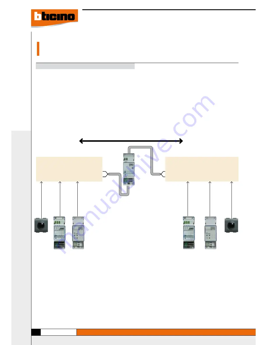
3. As indicated in the figure, the scenario modules item F420, the actuators
(including those configured as “master”) and the IR receivers item
HC/HS4654, L/N/NT4654N and item AM5834 are installed on the stretch
of bus 1 or 2 corresponding to their own local address. Example: if the
scenario module is configured as A=2, PL=1 it will be put on system 1.
4. Interface item F422 allows the transit between the various systems of the
Point-Point, Group, Room and General controls.
As an example, install a control configured A=1 and PL=5 in system 2 to
control actuator A=1 and PL=5 installed in system 1.
Automation system No. 1
addresses included
between A = 1 PL = 1
and A = 3 PL = 1
Point-Point, Group, Room and General Controls
BUS
BUS
I1= —
I2= —
I3 = 3
I4 = 2
MOD = 1
Interface
F422
Scenario
module
Actuator (*)
Automation system No. 2
addresses included
between A = 3 PL = 3
and A = 9 PL = 9
Actuator (*)
IR receiver
IR receiver
Scenario
module
NOTE (*): except the actuators in “SLAVE” mode which can be
connected both in system No. 1 and in system No. 2.


