


9
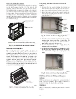
1/2-20 UNF RH
30
0.596
.47
5/8” HEX
SEAT
CORE
WASHER
DEPRESSOR PER ARI 720
+.01/-.035
FROM FACE OF BODY
7/16-20 UNF RH
O-RING
45
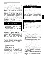
torqued into the seat. Appropriate handling is
required to not scratch or dent the surface.
1/2" HEX
This surface provides a metal to metal seal when
o
o
(Part No. EC39EZ067)
C08453
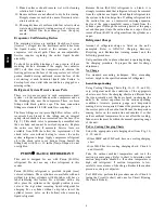
Fig. 9 -- CoreMax Access Port Assembly
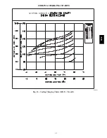
EXAMPLE:
Model 580J*14D
Circuit 1:
Outdoor Temperature
85
_
F (29
_
C)
. . . . . . . . . . . . . . . . . .
Suction Pressure
125 psig (860 kPa)
. . . . . . . . . . . . . . . . .
Suction Temperature should be
58
_
F (14
_
C)
. . . . . . . . . .
Circuit 2:
Outdoor Temperature
85
_
F (29
_
C)
. . . . . . . . . . . . . . . . . .
Suction Pressure
120 psig (830 kPa)
. . . . . . . . . . . . . . . . .
Suction Temperature should be
60
_
F (16
_
C)
. . . . . . . . . .
580J
Summary of Contents for 580J*08--14D
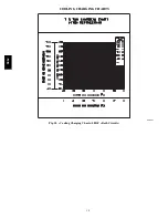
Page 10: ...10 COOLING CHARGING CHARTS C09221 Fig 10 Cooling Charging Charts 08D F Both Circuits 580J ...
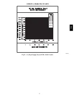
Page 11: ...11 COOLING CHARGING CHARTS C09222 Fig 11 Cooling Charging Charts 12D F Both Circuits 580J ...
Page 36: ...36 C07129 Fig 42 RTU MP Multi Protocol Control Board 580J ...
Page 37: ...37 C09163 Fig 43 Typical RTU MP System Control Wiring Diagram 580J ...
Page 60: ...60 C09156 Fig 73 580J Typical Unit Wiring Diagram Power 08D F 208 230 3 60 580J ...
Page 61: ...61 C09157 Fig 74 580J Typical Unit Wiring Diagram Control 08 12D F 208 230 3 60 580J ...
Page 84: ...84 580J ...


