


34
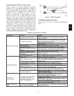
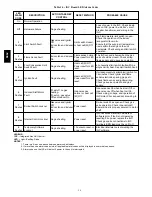
Table 14 – IGC Board LED Alarm Codes
LED
FLASH
CODE
DESCRIPTION
ACTION TAKEN BY
CONTROL
RESET METHOD
PROBABLE CAUSE
On
Normal Operation
—
—
—
Off
Hardware Failure
No gas heating.
—
Loss of power to the IGC. Check 5 amp
fuse on IGC, power to unit, 24V circuit
breaker, transformer, and wiring to the
IGC.
2
Flashes Limit Switch Fault
Gas valve and igniter
Off.
Indoor fan and inducer
On.
Limit switch closed,
or heat call (W) Off.
High temperature limit switch is open.
Check the operation of the indoor
(evaporator) fan motor.
Ensure that the supply-air temperature
rise is within the range on the unit
nameplate. Check wiring and limit switch
operation.
3
Flashes Flame Sense Fault
Indoor fan and inducer
On.
Flame sense normal.
Power reset for LED
reset.
The IGC sensed a flame when the gas
valve should be closed. Check wiring,
flame sensor, and gas valve operation.
4
Flashes
Four Consecutive Limit
Switch Fault
No gas heating.
Heat call (W) Off.
Power reset for LED
reset.
4 consecutive limit switch faults within a
single call for heat. See Limit Switch Fault.
5
Flashes Ignition Fault
No gas heating.
Heat call (W) Off.
Power reset for LED
reset.
Unit unsuccessfully attempted ignition for
15 minutes. Check igniter and flame
sensor electrode spacing, gaps, etc.
Check flame sense and igniter wiring.
Check gas valve operation and gas
supply.
6
Flashes
Induced Draft Motor
Fault
If heat off: no gas
heating.
If heat on: gas valve
Off and inducer On.
Inducer sense
normal, or heat call
(W) Off.
Inducer sense On when heat call Off, or
inducer sense Off when heat call On.
Check wiring, voltage, and operation of
IGC motor. Check speed sensor wiring to
IGC.
7
Flashes Rollout Switch Lockout
Gas valve and igniter
Off.
Indoor fan and inducer
On.
Power reset.
Rollout switch has opened. Check gas
valve operation. Check induced-draft
blower wheel is properly secured to motor
shaft.
8
Flashes Internal Control Lockout No gas heating.
Power reset.
IGC has sensed internal hardware or
software error. If fault is not cleared by
resetting 24 v power, replace the IGC.
Check gas valve connections to IGC
terminals. BRN lead must be on Pin 11.
9
Flashes
Temporary Software
Lockout
No gas heating.
1 hour auto reset, or
power reset.
Electrical interference is disrupting the
IGC software.
LEGEND
IGC
--- Integrated Gas Unit Control
LED
--- Light---Emitting Diode
NOTES
:
1. There is a 3---second pause between alarm code displays.
2. If more than one alarm code exists, all applicable alarm codes will be displayed in numerical sequence.
3. Alarm codes on the IGC will be lost if power to the unit is interrupted.
580J
Summary of Contents for 580J*08--14D
Page 10: ...10 COOLING CHARGING CHARTS C09221 Fig 10 Cooling Charging Charts 08D F Both Circuits 580J ...
Page 11: ...11 COOLING CHARGING CHARTS C09222 Fig 11 Cooling Charging Charts 12D F Both Circuits 580J ...
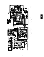
Page 36: ...36 C07129 Fig 42 RTU MP Multi Protocol Control Board 580J ...
Page 37: ...37 C09163 Fig 43 Typical RTU MP System Control Wiring Diagram 580J ...
Page 60: ...60 C09156 Fig 73 580J Typical Unit Wiring Diagram Power 08D F 208 230 3 60 580J ...
Page 61: ...61 C09157 Fig 74 580J Typical Unit Wiring Diagram Control 08 12D F 208 230 3 60 580J ...
Page 84: ...84 580J ...


