


53
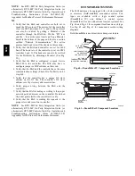
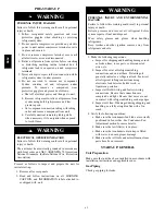
Supply Air Temperature (SAT) Sensor
The supply air temperature sensor is a 3 K thermistor
located at the inlet of the indoor fan. (See Fig. 65.) This
sensor is factory installed. The operating range of
temperature measurement is 0
°
to 158
_
F (--18
_
to 70
_
C).
See Table 16 for sensor temperature/resistance values.
SUPPLY AIR
TEMPERATURE
SENSOR
MOUNTING
LOCATION
SUPPLY AIR
TEMPERATURE
SENSOR
C06033
Fig. 65 -- Supply Air Sensor Location
The temperature sensor looks like an eyelet terminal with
wires running to it. The sensor is located in the “crimp
end” and is sealed from moisture.
Outdoor Air Lockout Sensor
The EconoMi$er IV is equipped with an ambient
temperature lockout switch located in the outdoor
airstream which is used to lock out the compressors below
a 42
_
F (6
_
C) ambient temperature. (See Fig. 60.)
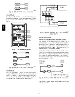
EconoMi$er IV Control Modes
IMPORTANT
: The optional EconoMi$er2 does not
include a controller. The EconoMi$er2 is operated by a 4
to 20 mA signal from an existing field-supplied controller.
See Fig. 63 for wiring information.
Determine the EconoMi$er IV control mode before set up
of the control. Some modes of operation may require
different sensors. (See Table 22.) The EconoMi$er IV is
supplied from the factory with a supply-air temperature
sensor and an outdoor-air temperature sensor. This allows
for operation of the EconoMi$er IV with outdoor air dry
bulb changeover control. Additional accessories can be
added to allow for different types of changeover control
and operation of the EconoMi$er IV and unit.
Outdoor Dry Bulb Changeover
The standard controller is shipped from the factory
configured for outdoor dry bulb changeover control. The
outdoor air and supply air temperature sensors are
included as standard. For this control mode, the outdoor
temperature is compared to an adjustable setpoint selected
on the control. If the outdoor-air temperature is above the
setpoint, the EconoMi$er IV will adjust the outside air
dampers to minimum position. If the outdoor-air
temperature is below the setpoint, the position of the
outside air dampers will be controlled to provided free
cooling using outdoor air. When in this mode, the LED
next to the free cooling setpoint potentiometer will be on.
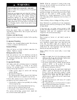
The changeover temperature setpoint is controlled by the
free cooling setpoint potentiometer located on the control.
(See Fig. 66.)
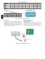
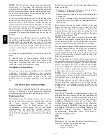
The scale on the potentiometer is A, B, C, and D. See Fig.
63 for the corresponding temperature changeover values.
C06034
Fig. 66 -- EconoMi$er IV Controller Potentiometer
and LED Locations
LED ON
LED ON
LED ON
LED ON
LED OFF
19
18
LED OFF
LED OFF
LED OFF
17
16
15
14
13
12
11
10
9
40
45
50
55
60
65
70
75
80
85
90
95 100
DEGREES FAHRENHEIT
mA
D
C
B
A
C06035
Fig. 67 -- Outside Air Temperature Changeover
Setpoints
0
5
10
15
20
25
30
0.13 0.20 0.22 0.25 0.30 0.35 0.40 0.45 0.50
STATIC PRESSURE (in. wg)
FLOW
IN
CUBIC
FEET
PER
MINUTE
(cfm)
C06031
Fig. 68 -- Outdoor--Air Damper Leakage
580J
Summary of Contents for 580J*08--14D
Page 10: ...10 COOLING CHARGING CHARTS C09221 Fig 10 Cooling Charging Charts 08D F Both Circuits 580J ...
Page 11: ...11 COOLING CHARGING CHARTS C09222 Fig 11 Cooling Charging Charts 12D F Both Circuits 580J ...
Page 36: ...36 C07129 Fig 42 RTU MP Multi Protocol Control Board 580J ...
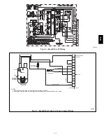
Page 37: ...37 C09163 Fig 43 Typical RTU MP System Control Wiring Diagram 580J ...
Page 60: ...60 C09156 Fig 73 580J Typical Unit Wiring Diagram Power 08D F 208 230 3 60 580J ...
Page 61: ...61 C09157 Fig 74 580J Typical Unit Wiring Diagram Control 08 12D F 208 230 3 60 580J ...
Page 84: ...84 580J ...


