


33
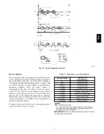
Minimum Heating Entering Air Temperature
When operating on first stage heating, the minimum
temperature of air entering the dimpled heat exchanger is
50
_
F continuous and 45
_
F intermittent for standard heat
exchangers and 40
_
F continuous and 35
_
F intermittent for
stainless steel heat exchangers. To operate at lower
mixed--air temperatures, a field--supplied outdoor--air
thermostat must be used to initiate both stages of heat
when the temperature is below the minimum required
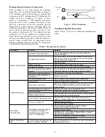
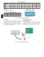
temperature to ensure full fire operation. Wire the
outdoor--air thermostat OALT (part no. HH22AG106) in
series with the second stage gas valve. (See Fig. 41.) Set
the outdoor--air thermostat at 35
_
F for stainless steel heat
exchangers or 45
_
F for standard heat exchangers. This
temperature setting will bring on the second stage of heat
whenever the ambient temperature is below the thermostat
setpoint. Indoor comfort may be compromised when
heating is initiated using low entering air temperatures
with insufficient heating temperature rise.
LCTB
W2
Thermostat
TH1
TH2
W1
W1
W2
OALT
C08442
Fig. 41 -- OATL Connections
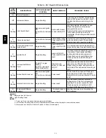
Troubleshooting Heating System
Refer to Table 13 and 14 for additional troubleshooting
topics.
Table 13 – Heating Service Analysis
PROBLEM
CAUSE
REMEDY
Burners Will Not Ignite.
Misaligned spark electrodes.
Check flame ignition and sensor electrode positioning.
Adjust as needed.
No gas at main burners.
Check gas line for air, purge as necessary. After purging
gas line of air, allow gas to dissipate for at least 5 minutes
before attempting to relight unit.
Check gas valve.
Water in gas line.
Drain water and install drip leg to trap water.
No power to furnace.
Check power supply, fuses, wiring, and circuit breaker.
No 24 v power supply to control
circuit.
Check transformer. Transformers with internal overcurrent
protection require a cool down period before resetting.
Miswired or loose connections.
Check all wiring and wire nut connections.
Burned---out heat anticipator in
thermostat.
Replace thermostat.
Broken thermostat wires.
Run continuity check. Replace wires, if necessary.
Inadequate Heating.
Dirty air filter.
Clean or replace filter as necessary.
Gas input to unit too low.
Check gas pressure at manifold. Clock gas meter for input.
If too low, increase manifold pressure, or replace with
correct orifices.
Unit undersized for application.
Replace with proper unit or add additional unit.
Restricted airflow.
Clean filter, replace filter, or remove any restrictions.
Blower speed too low.
Use high speed tap, increase fan speed, or install optional
blower, as suitable for individual units.
Limit switch cycles main burners.
Check rotation of blower, thermostat heat anticipator
settings, and temperature rise of unit. Adjust as needed.
Too much outdoor air.
Adjust minimum position.
Check economizer operation.
Poor Flame
Characteristics.
Incomplete combustion (lack of
combustion air) results in:
Aldehyde odors, CO, sooting
flame, or floating flame.
Check all screws around flue outlets and burner
compartment. Tighten as necessary.
Cracked heat exchanger.
Overfired unit — reduce input, change orifices, or adjust
gas line or manifold pressure.
Check vent for restriction. Clean as necessary.
Check orifice to burner alignment.
Burners Will Not Turn
Off.
Unit is locked into Heating mode
for a one minute minimum.
Wait until mandatory one---minute time period has elapsed
or reset power to unit.
580J
Summary of Contents for 580J*08--14D
Page 10: ...10 COOLING CHARGING CHARTS C09221 Fig 10 Cooling Charging Charts 08D F Both Circuits 580J ...
Page 11: ...11 COOLING CHARGING CHARTS C09222 Fig 11 Cooling Charging Charts 12D F Both Circuits 580J ...
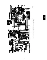
Page 36: ...36 C07129 Fig 42 RTU MP Multi Protocol Control Board 580J ...
Page 37: ...37 C09163 Fig 43 Typical RTU MP System Control Wiring Diagram 580J ...
Page 60: ...60 C09156 Fig 73 580J Typical Unit Wiring Diagram Power 08D F 208 230 3 60 580J ...
Page 61: ...61 C09157 Fig 74 580J Typical Unit Wiring Diagram Control 08 12D F 208 230 3 60 580J ...
Page 84: ...84 580J ...


