


49
Table 19 – Manufacture Date
When troubleshooting, you may need to know a control module’s manufacture date
Obtain the manufacture date from
a...
Notes
Module status report (modstat)
To obtain a modstat with BACview
6
:
1. Press Function (FN) key and hold.
2. Then press period (.)
3. Release both buttons.
The report shows the date under
Main board hardware
.
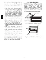
Sticker on the back of the main control
module board
”Serial No: RMPYMxxxxN”
(Bar Coded & Typed Number)
The serial numbers are unique and contain embedded information:
“RMP”
---
These first three digits are unique to RTU---MP and are used as an identifier.
“YM”
---
These two digits identify the last digit of the year and month (in hex, A=10/Oct)
of manufacture. ”74” would represent a date of manufacture of ”April 2007”.
“
xxxx”
---
These four digits represent the sequential number of units produced for a given
product for the mentioned manufacturing time period.
“N”
---
This final digit represents the decade and toggles between ”N” and ”M” every
ten years.
Table 20 – Basic Protocol Troubleshooting
Problem
Possible cause
Corrective action
No communication with 3rd
party vendor
Incorrect settings on SW1, SW2 and SW3
Verify and correct switch settings. Cycle
power to RTU---MP after changing switch
settings.
RS485 Port has no voltage output
Verify RTU---MP has correct power supply
(check with RTU---MP disconnected from RS485
communication bus)
Possible bad driver on board.
Bacnet @ 9600/19.2K --- .01 to .045vdc
Check RS485 bus for external before
reconnecting to the bus
Bacnet @ 38.4K --- .06 to .09vdc
Voltage, shorts or grounding
Bacnet @ 76.8K --- .1vdc
before reconnecting to the bus
Modbus @ 9600 --- 76.8K --- .124vdc
N2 @ 9600 --- .124vdc
Verify devices are daisy chained and repeaters and bias
terminators are correctly installed
Check 3rd party vendor RS485
communication wiring guidelines and
troubleshooting procedures
Table 21 – Modbus Exception Codes that May be
Returned From This Controller
CODE
NAME
MEANING
01
Illegal Function
The Modbus function code used
in the query is not supported by
the controller.
02
Illegal Data Address
The register address used in the
query is not supported by the
controller.
04
Slave Device Failure
The Modbus Master has
attempted to write to a
non---existent register or a
read---only register in the
controller.
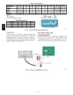
Modbus
1. Verify that the BAS and controller are both set to
speak the Modbus RTU protocol. The protocol of the
controller is set via SW3 (switches 3, 4, 5, and 6).
The protocol can also be verified by getting a Modstat
of the controller through the BACview. Hit the ”FN”
key and the ’.’ key at the same time to pull up a
Modstat. Scroll to the bottom of the page and there is
a section entitled “Network Communications.” The
active protocol and baud rate will be shown in this
section.
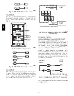
2. Verify that the BAS and controller are set for the
same baud rate. The baud rate of the controller is set
via SW3 (switches 1 and 2). The baud rate can also
be verified via the BACview by obtaining a Modstat
(See Fig. 59).
3. Verify that the BAS is configured to speak 2--wire
EIA--485 to the controller. The BAS may have to
configure jumper or DIP switches on their end.
4. Verify that the BAS and the controller have the same
communication settings (8 data bits, No Parity, and 1
stop bit).
5. Verify that the controller has a unique Modbus slave
address. The controller’s Modbus slave address is set
by its rotary address switches.
6. Verify that the BAS is using the proper Modbus
function codes to access data from our controller.
Supported function codes are shown above.
7. Verify proper wiring between the BAS and the
controller.
8. Verify that the BAS is reading or writing to the proper
Modbus register numbers on the controller. Download
the latest points list for the controller to verify.
9. Verify that the BAS is sending his requests to the
proper slave address of our controller.
580J
Summary of Contents for 580J*08--14D
Page 10: ...10 COOLING CHARGING CHARTS C09221 Fig 10 Cooling Charging Charts 08D F Both Circuits 580J ...
Page 11: ...11 COOLING CHARGING CHARTS C09222 Fig 11 Cooling Charging Charts 12D F Both Circuits 580J ...
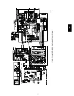
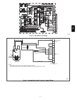
Page 36: ...36 C07129 Fig 42 RTU MP Multi Protocol Control Board 580J ...
Page 37: ...37 C09163 Fig 43 Typical RTU MP System Control Wiring Diagram 580J ...
Page 60: ...60 C09156 Fig 73 580J Typical Unit Wiring Diagram Power 08D F 208 230 3 60 580J ...
Page 61: ...61 C09157 Fig 74 580J Typical Unit Wiring Diagram Control 08 12D F 208 230 3 60 580J ...
Page 84: ...84 580J ...


